This document provides a comprehensive service manual for the YAMAHA ELECTRIC BASS TRB-4 II, detailing its overall assembly, electrical parts, circuit board, circuit diagram, wiring, and technical specifications. The TRB-4 II is a high-performance electric bass guitar designed for professional musicians, offering a blend of advanced electronics, quality craftsmanship, and versatile tonal capabilities.
Function Description
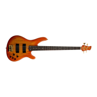
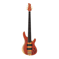
The YAMAHA TRB-4 II is a four-string electric bass guitar, part of Yamaha's TRB series known for its extended range and sophisticated electronics. Its primary function is to produce low-frequency sounds for musical accompaniment, suitable for a wide range of genres from jazz and fusion to rock and pop. The instrument features active electronics, which include a 3-band equalizer (Bass, Mid, Treble) and a panpot for blending the signals from its two pickups (front and rear). This active circuitry allows for precise tonal shaping and a powerful output signal, making it ideal for both live performances and studio recording.
The bass is equipped with two pickups, likely humbuckers, which are designed to capture the string vibrations and convert them into an electrical signal. The panpot allows the player to continuously blend between the front and rear pickups, offering a wide spectrum of tones from warm and round (neck pickup) to bright and punchy (bridge pickup). The 3-band equalizer further enhances this versatility, enabling players to boost or cut specific frequency ranges to tailor their sound to different musical contexts or personal preferences. The volume control adjusts the overall output level of the instrument.
The TRB-4 II's design emphasizes playability and ergonomic comfort. The neck is crafted for smooth navigation across the fretboard, and the body shape is contoured to provide a comfortable playing experience whether seated or standing. The hardware components, including the bridge and tuning machines, are selected for their stability and reliability, ensuring consistent tuning and intonation.
Important Technical Specifications
The manual provides detailed specifications for various components of the TRB-4 II:
Standard Specifications:
- Scale Length: 863.6mm
- Body/Neck Construction: Bolt On
- Length: 1147.0mm
- Width: 334.5mm
- Net Weight: 4.2kg
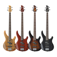
Color:
- Body: Amber Burst, Magenta Burst, Translucent Blue
- Neck: Amber Burst, Magenta Burst, Translucent Blue
Body:
- Material: Light Ash
- Body Depth: 41.0mm
Fingerboard:
- Material: Rosewood
- Fingerboard Width: 0-F 40.0mm, 12-F 56.9mm
- No. of Frets: 24
Neck:
- Material: Maple
- Neck Thickness: 1-F 20.7mm, 12-F 25.7mm
Parts:
- Hardware: Gold Plated
- Nut: Bone
- Bridge: BPX-4C Gold (YAMAHA I4030)
- Strings: YAMAHA I4030
Controls:
- Volume: 5kΩ x1
- Balance: 20kΩ x1
- Equalizer: 50kΩ x3
Pickups:
- Front/Rear: Double Coil
- Magnet: Alnico-V
Electrical Parts:
The active electronics are powered by a 9V battery, as indicated in the circuit diagram. Key electrical components include:
- IC: IX087770 (OP AMP), IX087780 (OP AMP), IX087790 (OP AMP), IX087800 (OP AMP), IX087810 (IC), IX087820 (IC)
- Diode: IX080900 (Diode)
- Potentiometers: QC183900 (Volume), HX080160 (Panpot), HX080160 (Equalizer Bass), HX080160 (Equalizer Mid), HX080160 (Equalizer Treble)
- Connectors: LB918020 (Connector), LB918020 (Connector), LB918020 (Connector)
- Capacitors: A wide range of ceramic, electrolytic, mylar, and tantalum capacitors with various capacitance values (e.g., 0.01uF, 0.022uF, 10uF, 100uF) and voltage ratings (e.g., 16V, 25V, 50V, 100V).
- Resistors: Carbon resistors with various resistance values (e.g., 1K, 4.7K, 10K, 22K, 33K, 47K, 68K, 100K) and power ratings (1/6W J).
Usage Features
The TRB-4 II is designed for a versatile playing experience:
- Active Electronics: The 3-band EQ and panpot provide extensive tonal control, allowing players to dial in a wide array of sounds suitable for different musical styles. The active circuit ensures a strong, clear signal with minimal noise.
- Pickup Blending: The panpot allows for seamless blending between the neck and bridge pickups, offering a spectrum of tones from deep and warm to bright and articulate.
- Ergonomic Design: The body shape and neck profile are crafted for comfort and playability, facilitating extended playing sessions without fatigue. The 24-fret rosewood fingerboard provides a wide range for expressive playing.
- High-Quality Hardware: Gold-plated hardware, including the BPX-4C bridge and reliable tuning machines, ensures tuning stability and durability.
- Bolt-On Construction: The bolt-on neck construction contributes to the instrument's punchy attack and sustain, a characteristic often favored by bassists.
- Light Ash Body: The light ash body contributes to the instrument's resonant tone and manageable weight.
Maintenance Features
The manual provides critical information for maintenance and repair:
- Overall Assembly Diagram: This diagram (Page 2) illustrates the placement of all major components, including the bridge assembly, tuning machines, pickups, controls, and neck. This is crucial for disassembling and reassembling the instrument correctly.
- Electrical Parts List: Pages 3-5 provide a detailed list of all electrical components, including their reference numbers, part numbers, descriptions, and quantities. This is essential for identifying and ordering replacement parts.
- Circuit Board Layout: Page 6 shows the layout of the circuit board (Pattern side and Component side), indicating the placement of various resistors, capacitors, and integrated circuits. This is vital for troubleshooting electronic issues and performing component-level repairs.
- Circuit Diagram: Page 7 presents the complete circuit diagram, illustrating the connections between all electrical components, including the pickups, controls, active EQ, and output jack. This diagram is indispensable for diagnosing wiring problems and understanding the signal flow.
- Wiring Diagram: Page 8 provides a simplified wiring diagram, showing the connections between the pickups, controls (volume, panpot, EQ), and output jack. This is helpful for understanding the basic electrical connections and for performing routine wiring checks.
- Warning: Chemical Content Notice: The manual includes an important warning regarding lead content in solder and other electrical/electronic parts. It advises against using lead-based solder for repairs and emphasizes proper disposal of components. This highlights the importance of using lead-free solder and following environmental regulations during maintenance.
- Soldering Precautions: The warning also advises against prolonged contact with solder and flux fumes, recommending good ventilation. It also warns against touching components or solder joints with bare hands after soldering, emphasizing the need for proper cleaning to remove flux residue. These precautions are crucial for technician safety and the longevity of repairs.
- Battery Replacement: While not explicitly detailed as a step-by-step process, the circuit diagram indicates a "Battery 9V" connection, implying that regular battery replacement will be necessary for the active electronics to function. Access to the battery compartment is typically on the back of the instrument.
In summary, the YAMAHA TRB-4 II is a sophisticated electric bass guitar designed for professional use, offering extensive tonal flexibility through its active electronics and high-quality construction. The service manual provides comprehensive information for maintenance, troubleshooting, and repair, ensuring the instrument can be kept in optimal working condition for years to come.