EasyManua.ls Logo

Yamaha TX7 - Page 2

Yamaha TX7
27 pages
Print Icon
To Next Page IconTo Next Page
To Previous Page IconTo Previous Page
Loading...
TX7
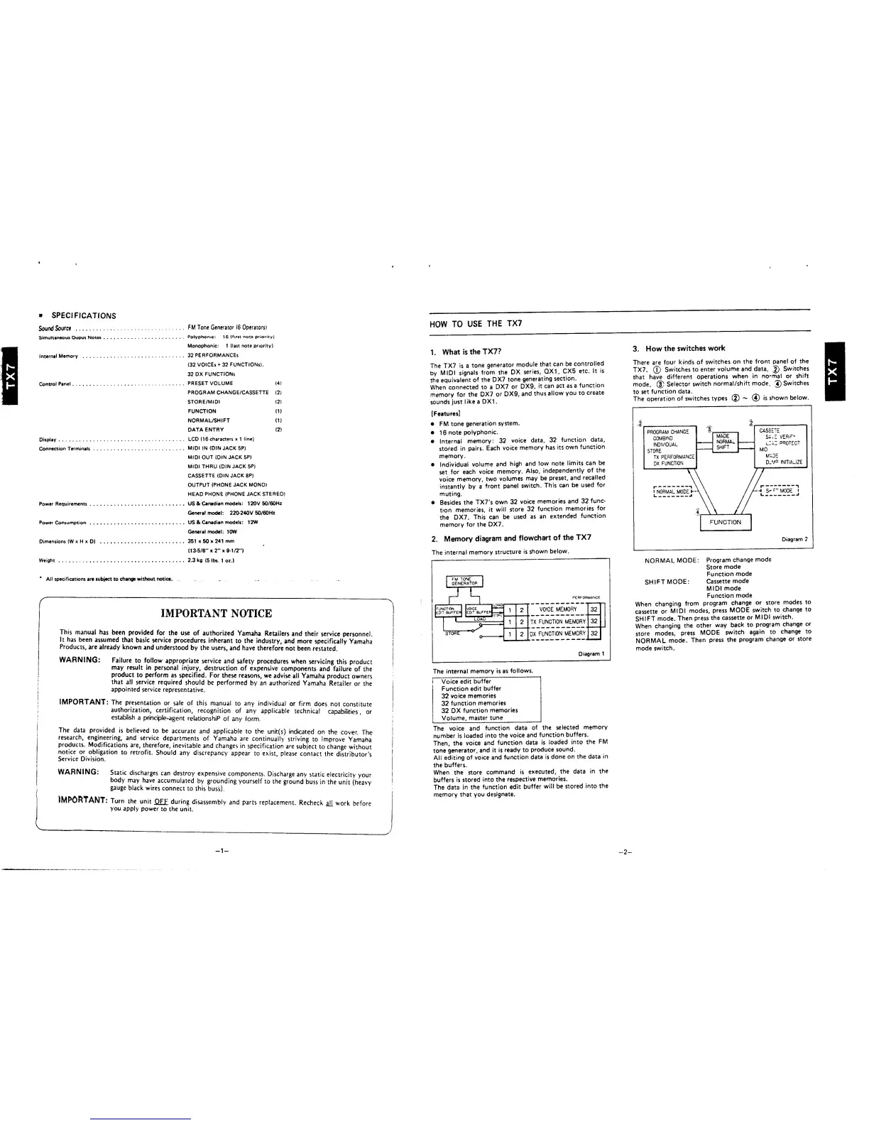
SPECIFICATIONS
SoundSource
Simultaneous
Ouput
Notes ....
Internal
Memory
Control
Panel
Display
Connection
Terminals
Power Requirements
. .
Power Consumption
. .
Dimensions
(WxHxD)
Weight
FM Tone
Generator
(6
Operators}
Polyphonic;
16
(first
note
priority)
Monophonic:
1
(last note priority)
32
PERFORMANCES
(32
VOICES
+
32
FUNCTIONS),
32
DX
FUNCTIONS
PRESET
VOLUME
(4)
PROGRAM CHANGE/CASSETTE
(2)
STORE/MIDI
(2)
FUNCTION
(1)
NORMAL/SHIFT
(1)
DATA
ENTRY
(2)
LCD <16
characters
x
1
line)
MIDI IN
(DIN
JACK SP)
MIDI OUT
(DIN
JACK
5P)
MIDI THRU (DIN
JACK
5P)
CASSETTE
(DIN JACK
8P)
OUTPUT
(PHONE JACK MONO)
HEAD
PHONE (PHONE JACK
STEREO)
US &
Canadian
models:
1 20V
50/60HZ
General model: 220-240V
50/60HZ
US
&
Canad
Ian
models
: 1
2W
General model; 10W
351 x
50
x
241
mm
113-5/6"
x
2”
x
9-1/2")
2.3
kg
(5
lbs. 1 oz.)
*
All specifications
are subject to
change without notice.
.
—
-N
IMPORTANT
NOTICE
This
manual
has been
provided
for
the use
of
authorized
Yamaha
Retailers and
their
service
personnel.
It has been
assumed
that
basic service
procedures
inherant
to
the
industry,
and
more
specifically
Yamaha
Products,
are already
known and
understood
by the users,
and have
therefore
not
been
restated.
WARNING:
Failure to
follow
appropriate
service
and safety
procedures
when
servicing
this
product
may
result
in
personal
injury,
destruction of
expensive
components
and failure
of
the
product
to perform
as
specified.
For these
reasons, we
advise
all
Yamaha
product
owners
that
all service
required
should be
performed
by
an
authorized
Yamaha
Retailer
or the
j
appointed
service
representative.
IMPORTANT:
The
presentation
or
sale of
this manual
to
any
individual
or
firm
does
not
constitute
authorization,
certification,
recognition
of any
applicable
technical
capabilities,
or
|
establish
a
principle-agent
relationship
of
any form,
;
j
The data provided
is
believed
to be
accurate
and applicable
to
the
unit(s)
indicated
on
the
cover.
The
research,
engineering,
and
service
departments
of Yamaha
are
continually
striving
to
improve
Yamaha
products.
Modifications
are,
therefore,
inevitable
and
changes in
specification
are
subject
to
change
without
notice or
obligation
to retrofit.
Should any
discrepancy
appear
to
exist, please
contact
the
distributor’s
Service
Division.
|
WARNING:
Static
discharges
can
destroy
expensive
components.
Discharge
any
static
electricity
your
body
may
have
accumulated
by grounding
yourself
to
the
ground
buss
in
the
unit
(heavy
gauge
black
wires
connect
to this
buss).
IMPORTANT:
Turn
the
unit
OFF
during
disassembly
and
parts
replacement.
Recheck
ail
work
before
you
apply
power
to the
unit.
,
HOW
TO
USE
THE
TX7
1.
What is
the
TX7?
The
TX7 is
a
tone
generator
module
that
can
be
controlled
by
MIDI
signals
from
the
DX
series,
QX1
,
CX5
etc.
It
is
the
equivalent
of
the
DX7
tone
generating
section.
When
connected to a
DX7
or
DX9,
it
can
act as a
function
memory
for the
DX7
or
DX9,
and
thus
allow
you
to
create
sounds
just
like
a
DX1
.
[Features]
•
FM tone
generation
system.
•
16
note
polyphonic.
•
Internal
memory:
32
voice
data,
32
function
data,
stored
in
pairs.
Each
voice
memory
has its
own
function
memory.
•
Individual
volume
and
high
and
low
note
limits
can be
set
for
each
voice
memory.
Also,
independently
of
the
voice
memory,
two
volumes
may be
preset,
and
recalled
instantly by a
front
panel
switch.
This
can
be
used
for
muting.
•
Besides
the
TX7's
own 32
voice
memories
and 32
func-
tion
memories,
it
will store
32
function
memories
for
the
DX7.
This can
be
used
as
an
extended
function
memory
for
the DX7.
2
.
Memory
diagram
and
flowchart
of
the TX7
The
internal
memory
structure
is
shown
below.
I FM TONE
1
GENERATOR
j
J
IT
T—
“1
PERFORMANCE
jCTST
1
|EDt7
buffe*}
|edit
Buffer}—..
1
2
VOICE
MEMORY
32
1
"
i
LOAD
9
1
2
TX
FUNCTION
MEMORY
32
STORE
0
1 2
DX
FUNCTION
MEMORY
32
Diagram 1
The
internal
memory is
as
follows.
;
Voice edit
buffer
Function
edit
buffer
32
voice
memories
32
function
memories
32
DX
function
memories
Volume,
master
tune
The
voice and
function
data
of
the
selected
memory
number
is
loaded
into
the
voice
and
function
buffers.
Then, the
voice
and
function
data is
loaded into
the
FM
tone
generator,
and it
is
ready
to
produce
sound.
All
editing
of
voice
and
function
data
is
done
on
the
data
in
the
buffers.
When
the
store
command
is
executed,
the data
in
the
buffers is
stored
into
the
respective
memories.
The data
in
the
function
edit
buffer
will
be
stored
into
the
memory that
you
designate.
3.
How
the
switches
work
There are
four
kinds
of
switches on
the from
panel
of
the
TX7.
0
Switches to
enter
volume
and data,
0
Switches
that
have
different
operations
when
in
normal
or
shift
mode,
®
Selector
switch
normat/shift
mode,
0
Switches
to set
function
data.
The
operation
of switches
types
0
^
0
is
shown
below.
Diagram
2
NORMAL
MODE:
Program
change
mode
Store
mode
Function
mode
SH
I
FT
MODE
:
Cassette
mode
MIDI
mode
Function
mode
When
changing
from
program
change
or
store
modes to
cassette
or
MIDI
modes,
press
MODE
switch
to
change
to
SHIFT
mode.
Then press
the
cassette
or
MIDI
switch.
When
changing
the
other
way
back to
program
change
or
store
modes,
press
MODE
switch
again
to
change
to
NORMAL
mode.
Then
press
the
program
change
or
store
mode
switch.
-
1
-
—
2
—
TX7