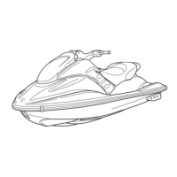
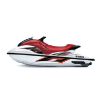
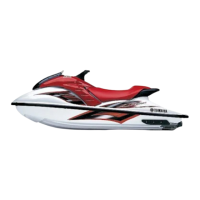
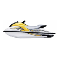
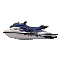
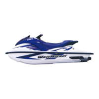
Do you have a question about the Yamaha WaveRunner GP800R and is the answer not in the manual?
Explains the sequential, step-by-step format of procedures and component condition indicators.
States that illustrations represent all designated models.
Notes that cross references are minimized and direct to appropriate sections.
Explains the safety alert symbol means "ATTENTION! BECOME ALERT! YOUR SAFETY IS INVOLVED!".
Defines warnings related to severe injury or death.
Defines cautions related to avoiding damage to the watercraft.
Explains notes provide key information for easier procedures.
Notes changes in specifications during production.
Lists symbols 1-9 indicating chapter content.
Lists symbols 0-E indicating specific data like tools, torque, etc.
Lists symbols F-H for lubricant grades and locations.
Lists symbols I-N for sealing/locking agents and application points.
Details primary I.D., engine serial, jet pump serial, and hull identification numbers.
Covers fire prevention, ventilation, self-protection, and good working practices.
Lists specialized tools required for maintenance and repair.
Covers measurement procedures and tools.
Outlines procedures for removing and installing parts.
Provides overall specifications for the watercraft model.
Details specifications for engine, jet pump, hull, and electrical components.
Lists specified tightening torques for various parts and assemblies.
Illustrates how cables and hoses should be routed for proper operation.
Provides a guide for general maintenance intervals based on hours or time.
Details routine checks and adjustments for various systems like control, fuel, and power units.
Covers general inspection items like drain plugs and lubrication points.
Details the fuel cock and filter assembly, including exploded views and service points.
Covers the oil tank, its components, removal, installation, and inspection.
Explains the fuel tank, its parts, removal, installation, and inspection procedures.
Describes the intake silencer, its components, removal, and installation.
Details the carburetor unit, including exploded diagrams, removal/installation, and service points.
Details the step-by-step disassembly of the carburetor.
Explains how to disassemble the accelerator pump.
Details the step-by-step disassembly of the fuel pump.
Details the steps for removing the oil pump assembly.
Explains the removal of oil pump hoses and cables.
Covers the engine unit, including exploded diagrams, removal/installation, and service points.
Details the exhaust chamber assembly, its components, and removal/installation.
Explains the exhaust chamber joint, its parts, and removal/installation.
Describes the exhaust manifold, its components, and removal/installation.
Covers reed valves, their components, removal/installation, and inspection.
Details the YPVS system, including exploded diagrams and service points.
Explains the cylinder head, its components, removal/installation, and inspection.
Details the steps for removing the cylinders and their inspection.
Covers piston removal, inspection of piston diameter, wall, and ring grooves.
Details the steps for removing the starter motor.
Covers flywheel magneto removal, installation, and inspection of related components.
Details the steps for disassembling and installing the crankcase.
Covers crankshaft removal and inspection of width, deflection, and clearances.
Overview of the jet pump unit, including exploded diagrams and removal/installation.
Details the nozzle deflector and ring, their components, and removal/installation.
Covers impeller duct, housing, and intake duct, including diagrams and removal/installation.
Details the impeller duct and drive shaft, including disassembly, inspection, and installation.
Explains the transom plate and hoses, their components, and service points.
Covers the bearing housing, its components, removal/installation, and service points.
Provides an overview of the watercraft's electrical components.
Details the electrical box, its components, and disassembly/installation.
Covers diagnostic procedures for electrical systems using testers.
Explains the ignition system, including wiring diagrams, spark plugs, and coils.
Details the starting system, including wiring, battery, fuses, and switches.
Covers the starter motor, its components, removal/installation, and inspection.
Provides the wiring diagram for the charging system.
Shows the wiring diagram for the YPVS system.
Details the removal and installation of the YPVS servomotor.
Covers inspection of the YPVS cables.
Explains how to inspect the YPVS servomotor.
Provides the wiring diagram for the indication system.
Covers buzzer inspection.
Details oil level sensor inspection.
Details fuel level sensor inspection.
Covers multifunction meter inspection and removal.
Covers the handlebar, its components, removal, installation, and inspection.
Details the QSTS grip, its components, removal, installation, and inspection.
Explains the steering column, its components, removal, installation, and inspection.
Covers remote control cables and speed sensor lead, including diagrams and service points.
Describes the front hood, its components, and removal/installation.
Details the steering console cover, its components, and removal/installation.
Details the steps for removing the buzzer and hood lock.
Details the steps for removing various hoses.
Covers inspection of the check valve.
Details the steps for removing seats and hand grips.
Covers inspection of the seat lock mechanism.
Details the steps for removing the battery box.
Details the steps for removing the exhaust system.
Covers the sub-assembly of exhaust system components.
Details the steps for disassembling the deck and hull.
Details the steps for removing the engine mount.
Covers procedures for repairing shallow and deep scratches on the hull.
Provides a chart to diagnose problems by checking related items and reference chapters.
| Manufacturer | Yamaha |
|---|---|
| Model | WaveRunner GP800R |
| Category | Boat |
| Engine Type | 2-cylinder, 2-stroke |
| Displacement | 784 cc |
| Fuel Capacity | 15.9 gallons |
| Fuel Type | Gasoline |
| Bore x Stroke | 82 x 74 mm |
| Cooling System | Water-cooled |
| Starting System | Electric |
| Seating Capacity | 2 |
| Fuel Delivery | Dual Carburetor |
| Passenger Capacity | 2 |
