Page of 11
Assembly
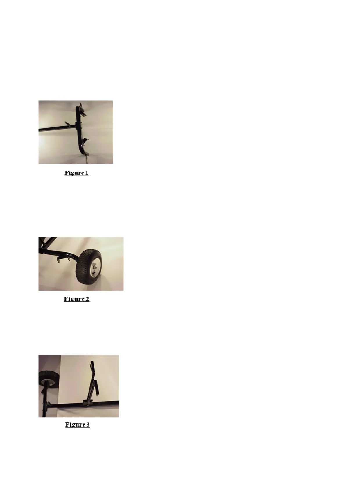
STEP 1: ATTACH TONGUE TO AXLE
Place tongue assembly (#4) and axle assembly (#1) on a flat surface. Position the tongue so that
the diameter of 19mm x length of 118mm shaft welded to the tongue is straight up. Orientate the
axle (#1) so the lift arm hinges welded to the axle face away from the tongue. See figure 1. Connect
the tongue (#4) to the axle (#1) using two 5/16”x2” hex bolts (B), two 5/16” nylock nuts (M). Fully
tighten connections.
STEP 2: ATTACH WHEELS TO AXLE
Assemble the tire/wheel assembly (#3) (inflation valve stem facing out) onto axle, securing the
tire/wheel with one 9/16” nylock nut (H). See figure 2. Repeat on opposite side of axle. CAUTION:
DO NOT over tighten the lock nut; this can result in damage to the bearings in the wheel hub. When
properly tightened, the wheel should spin freely.
STEP 3: ATTACH LIFT HANDLE TO TONGUE
Attach the lift handle (#7) to the top of the tongue (#4) where two holes are located. See figure 3 for
position of lift handle on tongue. Secure using two 5/16”x2” (B) hex bolts, two 5/16” nylock nuts (M).
Fully tighten connections.
 Loading...