ASSEMBLY INSTRUCTIONS
NOTE: This unit is shipped WITHOUT
OIL and GASOLINE. After assembly,
refer to separate engine manual for
proper fuel and engine oil recommen
-
dations.
CONTENTS OF HARDWARE PACK
(2) Ignition Keys (One may be on
snowthrower)
(1) Cotter Pin
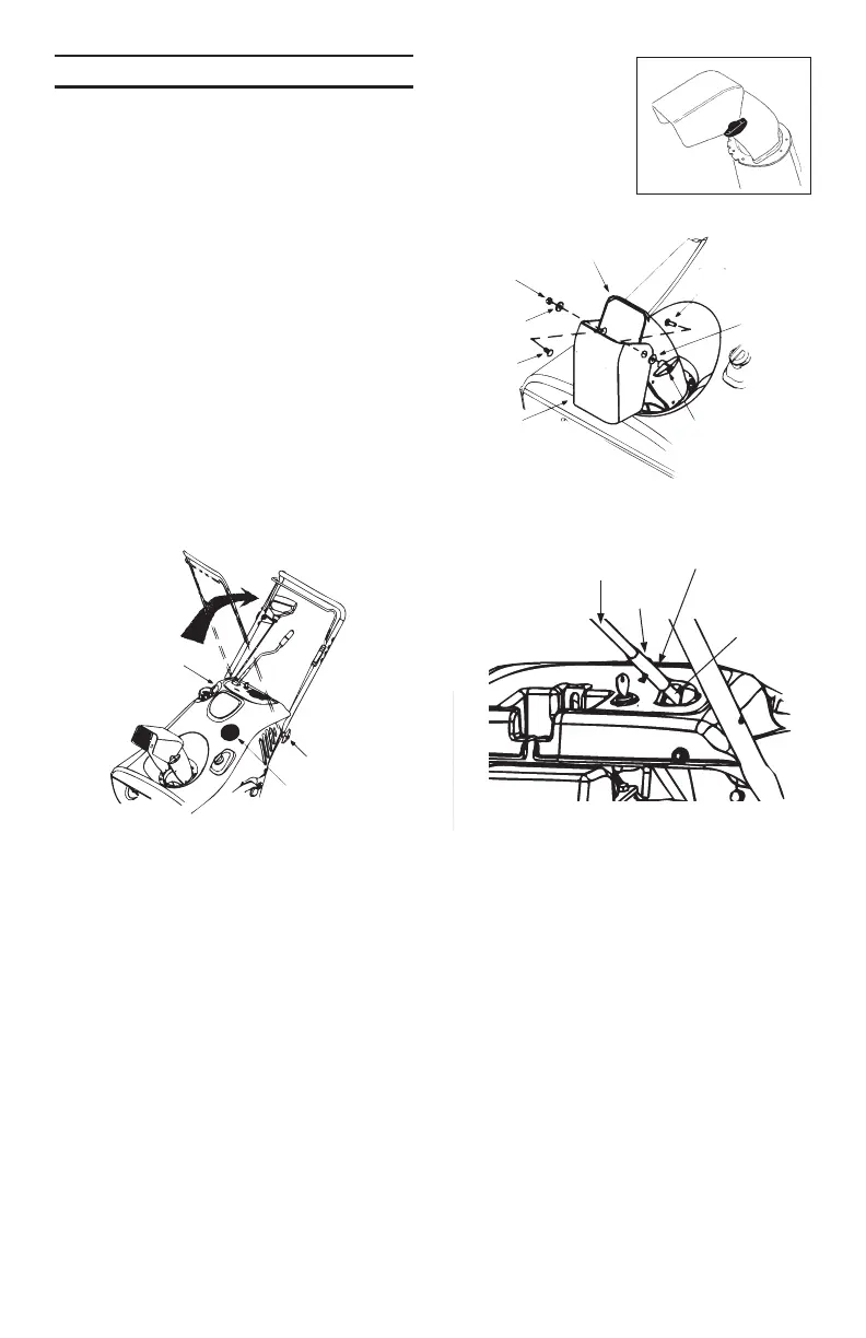
RAISING THE UPPER HANDLE
•
Loosen the handle knobs on each side of
the handle. Remove packing material, if
any.
•
Pull up and back on the upper handle to
raise the handle into the operating posi
-
tion. See Figure 1. Caution: Be careful
not to bend or kink the cables.
•
Tighten the handle knobs on each side of
the handle.
ASSEMBLING THE CHUTE
•
Remove the hand knob, cupped washer,
flat washer and carriage bolt from the up
-
per chute. See figure 2.
•
Pivot the upper chute up into operating
position (so there is no gap between the
upper and lower chute). See figure 2, in
-
sert. Secure with hardware just removed.
INSTALLING THE CHUTE CRANK
•
Place the cardboard from the carton on a
level surface. Tip the snowthrower forward
so that the housing rests on the card
-
board.
•
Connect the coupler on the upper chute
crank rod onto the lower chute crank rod
at the rop right side of the snowthrower.
See figure 3.
•
Rotate the crank to align holes, and se
-
cure with cotter pin (from the bag with the
manuals). Bend ends of cotter pin in op
-
posite directions to secure.
ATTACHING THE STARTER HANDLE
•
Remove spark plug access cover,
diconnect the spark plug and ground it
away from the spark plug as instructed in
the separate engine manual.
•
Press the auger control handle against
the upper handle and slowly pull the
starter rope out of the engine.
•
Insert the starter rope into the rope guide
bracket on the right hand side of the han
-
dle.
5
FIGURE 1
Handle
Knob
Handle
Knob
Spark Plug
Access
FIGURE 2
Carriage
Bolt
Flat
Washer
Flat
Washer
Upper
Chute
Hex Bolt
Nut
Lower
Chute
Handle
Knob
FIGURE 3
Coupler
Cotter Pin
Upper Chute
Crank Rod
Lower
Chute
Crank
Rod


 To Next Page