J'
./1
q.
SECTION 10: MAKING ADJUSTMENTS
WARNING: Never attempt to make any
adjustments while the engine
is
running,
except where specified
in
the operator's
manual.
WARNING: Disconnect the spark plug
wire(s) and ground against the engine before
performing any adjustments, repairs or
maintenance.
LEVELING THE DECK
NOTE: Check
the
tractor's tire pressure before
performing any deck leveling adjustments. Refer
to
TIRES
in
the maintenance section
of
this manual for
further information regarding tire pressure.
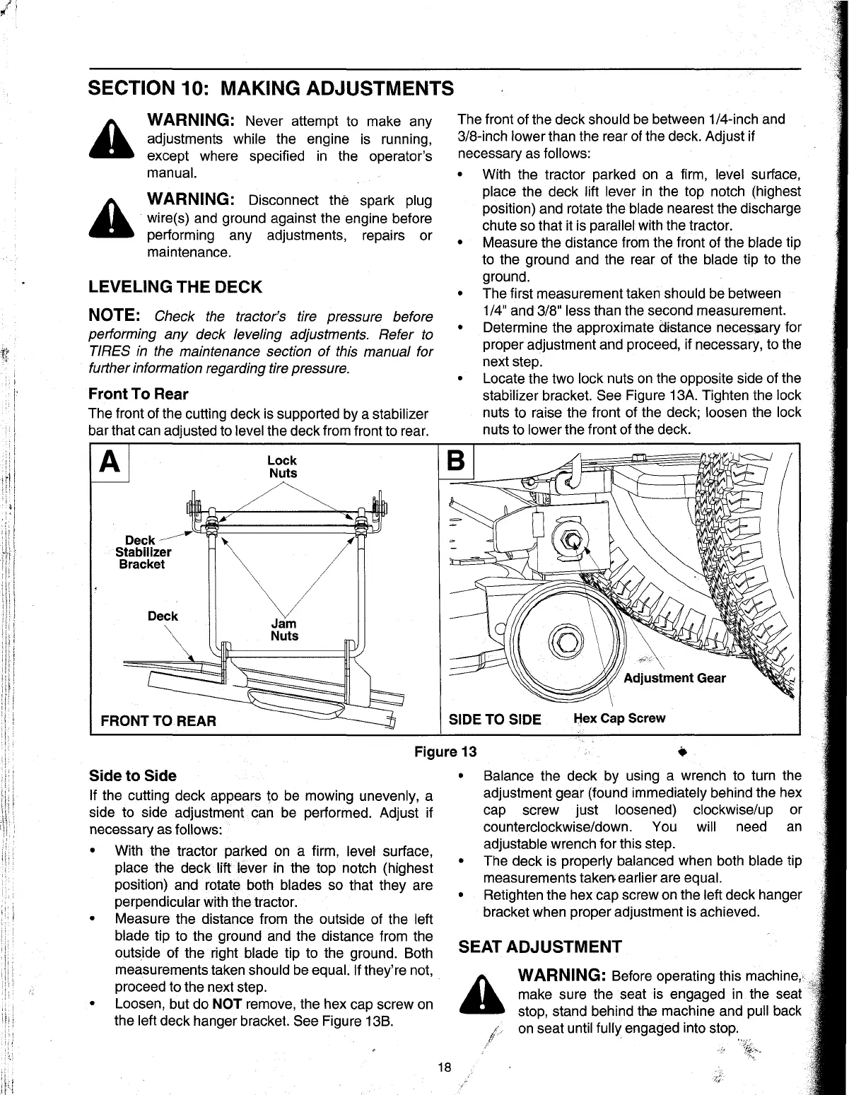
Front To Rear
The front of the cutting deck
is
supported by a stabilizer
bar that
can
adjusted to level the deck from front to rear.
Deck~
Stabilizer
Bracket
Deck
FRONT TO REAR
Lock
Nuts
Jam
Nuts
The front of the deck should
be
between 1/4-inch and
3/8-inch lower than the rear
of
the deck. Adjust if
necessary
as
follows:
•
•
•
•
•
With the tractor parked
on
a firm, level surface,
place the deck
lift lever
in
the top notch (highest
position) and rotate the blade nearest the discharge
chute so that
it
is parallel with the tractor.
Measure the distance from the front of the blade tip
to the ground and the rear of the blade tip to the
ground.
The first measurement taken should
be
between
1/4" and 3/8" less than the second measurement.
Determine the approximate
C&stance
necesiary for
proper adjustment and proceed, if necessary, to the
next step.
Locate the two
lock nuts
on
the opposite side of the
stabilizer bracket.
See Figure 13A. Tighten the lock
nuts to raise the front of the deck; loosen the lock
nuts to lower the front of the deck.
SIDE TO SIDE
Hex Cap Screw
Figure 13
Side
to
Side
If the cutting deck appears to
be
mowing unevenly, a
side to side adjustment can
be
performed. Adjust if
necessary as
follows:
•
With the tractor parked
on
a firm, level surface,
place the deck
lift lever in the top notch (highest
position) and rotate both blades so that they are
perpendicular with the tractor.
• Measure the distance from the outside of the left
blade tip to the ground and the distance from the
o(Jtside
of the right blade tip to the ground. Both
measurements taken should
be
equal. If they're not,
proceed to the next step.
• Loosen, but do NOT remove, the hex cap screw
on
the left deck hanger bracket. See Figure 13B.
18
•
•
•
Balance the deck by using a wrench to turn the
adjustment gear (found immediately behind the hex
cap screw just loosened) clockwise/up or
counterclockwise/down. You
will need
an
adjustable wrench for this step.
The deck is properly balanced when both blade tip
measurements
taken. earlier are equal.
Retighten the hex cap screw
on
the left deck hanger
bracket when proper adjustment
is
achieved.
SEAT ADJUSTMENT
WARNING: Before operating this machine"
make sure the seat
is
engaged
in
the seat
stop, stand behind
the machine and pull back
on
seat until fully engaged into stop.
 Loading...