Lock Nut M8 (×4)
3
Bolt Hole (×4)
Motor Base Bolt (×4)
2
1
Shaft
Bushing
1
2 3
Spring
M10×65 (×1)
Bracket
Figure 5b
Figure 6
TRANSMISSION & MOTOR
17
mm
× 2
13
mm
M10 × 65 × 1
8
× 1
M8 × 4
9
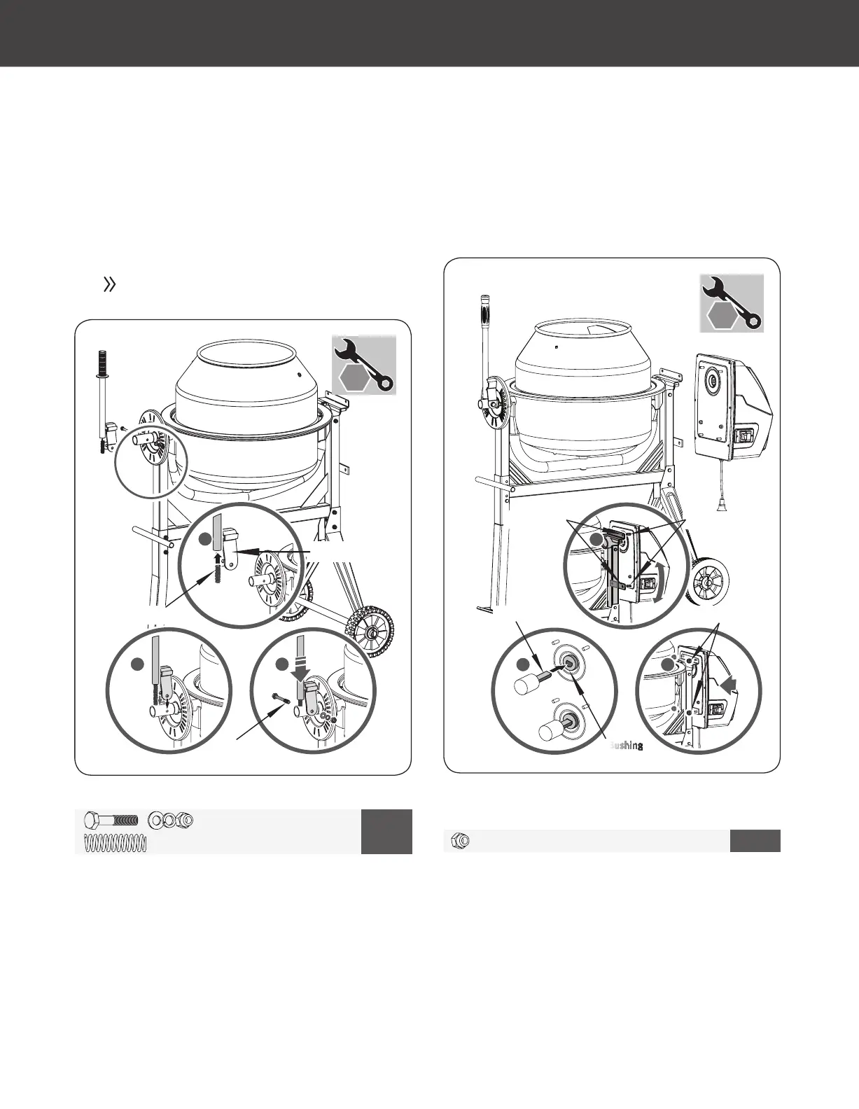
2. Insert the spring into the bar pipe, hold the spring in place with
a nger, and place the bar over the larger diameter shaft so the
spring stays inside the bar pipe. (See Figure 5b, Illustration 1)
Press down on bar pipe until the holes in the bracket line up
with the hole drilled in the shaft. (See Figure 5b, Illustration 2)
Insert a M10×65 hex bolt through the hole, place a at washer
on the bolt, and secure with nut. (See Figure 5b, Illustration 3)
Secure the nut against the bracket, do not overtighten as this
will prevent the bracket from pivoting on the bolt.
Align the pinion shaft with the bushing sleeve in the transmission
and slide into place. (See Figure 6, Illustration 1) Align the bolt
holes in the frame bracket with the bolt studs in the motor case
and slide into position. (See Figure 6, Illustration 2) Secure the
motor case to the frame bracket using four M8 lock nuts. (See
Figure 6, Illustration 3)
The bar must be allowed to pivot about the bolt
so that the lugs on the bracket can be engaged or
disengaged from the slots in the locking plate.
10
Electric Concrete Mixer
»
Operator’s Manual
Assembly
|
74013US25M101.indd 10 2017/3/14 11:28:44