18 19
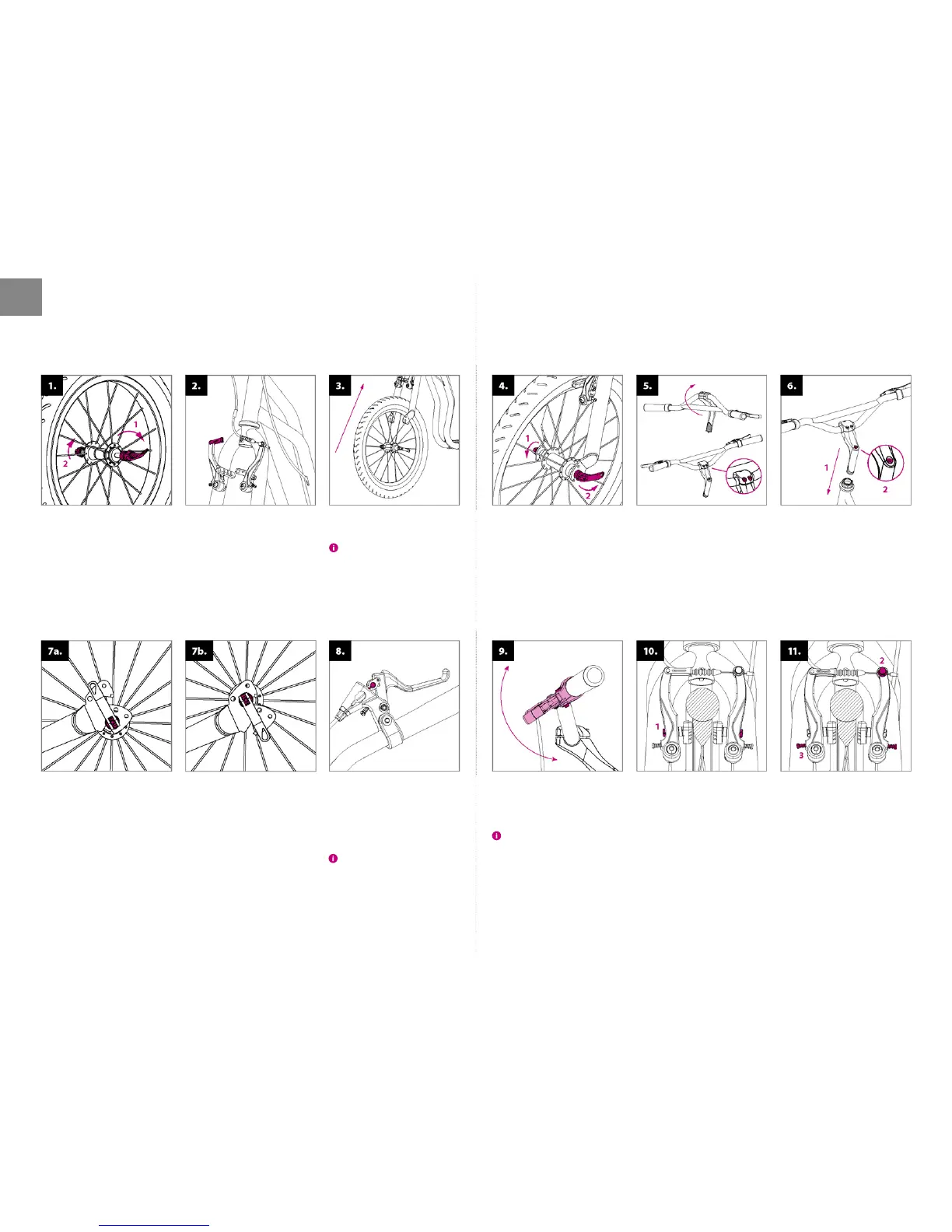
Place the wheel into the front fork
so that is well-centred.
The tread pattern (arrow-shaped lines
on the tires) must be pointing to the front.
Handlebar installation: place
the handlebar tube as shown
on the picture and tighten the
screws on the stem.
Insert the handlebar tube into the
front frame (1) and adjust the height
according to the rider’s needs
(not higher than indicated by the
line). Check that the handlebar is
upright and properly tighten the
screw on the handlebar tube (2).
ASSEMBLY INSTRUCTIONS
Make sure the front fork of the
scooter is well positioned (brake
levers are facing forward). Release
the brake cable from its holder
and loosen the brake arms.
Installation of brake cables:
press the brake lever to the maxi-
mum and insert the ending of the
brake cable into the circular xing
point. Repeat the action with
both brakes.
The rear brake cable is usually xed on
the right, front brake cable on the left.
Adjustment of brake levers:
incline the brake levers correctly
by loosening the screw on the
sleeve.
The right inclination: stand on the
footboard, hold the handles and stretch
out your ngers in away that your arm and
the ngers form asingle straight line. This
should be the position of the brake levers.
Adjustment of brakes: when
braking, check that the brake
pads of both wheels t tightly on
the rim sides. If not, you can ad-
just their position via ascrew that
connects them to the V-brake
arms (1). The pads shall not touch
the tires.
Assembly of the front (bigger)
wheel: open the quick-release
lever and loosen the nut.
Assembly of the rear wheel is
the same as the assembly of the
front wheel with the only excep-
tion of double dropout at the
rear fork. It allows positioning the
footboard according to the road
conditions. The lower dropout
enables o road riding.
The upper dropout, which also
makes the footboard go lower
and thus reduces the load on the
standing leg, is intended for at
surface. Riding will be less tiring.
Tighten the nut (1) until you can
feel resistance before closing the
quick release. Close it in away
that the quick release lever (2)
points backwards (for safety
reasons). Return the brake cable
into the holder.
Check that the pads make enough
space (1–2 mm) after releasing
the brake levers. The distance
can be adjusted by tightening or
loosening the brake cable at the
anchor screw (2).
In case the brake pad is touching
the wheel when turning, symmet-
rically adjust the distance of brake
arms by the tightening screws (3).
EN
 Loading...