EasyManua.ls Logo

YGE 205HVT - User Manual

YGE 205HVT
3 pages
Print Icon
To Next Page IconTo Next Page
Loading...
Speedcontroller YGE 205HVT
With BEC 12A / 30A
Technical data:
- The specified current is the maximum continuous full power current
- 4 to 14s LiPo, incl under voltage protection by power reduction
- 5 to 16s LiFePo4, incl under voltage protection by power reduction
- BEC 5,0V 8,4V
- BEC 12A continuous, 30A Peak
- Current limiting
- pluggable receiver- and telemetry cables with JST-socket
- Disconnectable under voltage detection
- Electronic speed control (Governor- mode)
- Soft start
- Active free-wheel, allowing unlimited part load operation.
- Automatic or 6 step adjustable timing
- Frequency: Automatic.
- Adjustable EMK brake
- F3A(Acro brake (brake force control infinitely adjustable)
- Speed limit: 240.000 rpm (2- Poles)
- Temperature and overload warning
- Anti- flash: decreases the closing spark.
- Basic -Programming with mode programming
- Fine adjustment and selection of telemetry log with the PC Setup
- Suitable USB-adapter optionally available
- Dimensions in mm: ca. 84 x 56 x 31
- Weight without / with wires: ca. 219g / 287g
- Cable diameter battery / motor: 6² / 6²
We point out that the mode-setup has to be
successfully done before using the controller!
(By using VBC + NEO not necessary)
(Look at the back page)
Mode 1: V- Stabi - Gov (external Governor)
Plug the RPM-output of the controller into the rpm/ tele in-put
of the receiver or FBL (for wire assignment see additional
page). Make sure that the wire of the rpm signal is parallel to
the negative wire of the receiver wire. Activate the rpm mode
of your FBL system.
Mode 2: Standard Governor Mode
When operating in Gov mode, the ESC can be used directly. If
you want to fly different RPM's and switch them in flight, you
have to start with at least 70%. Then you can switch over to
different RPM's.
Mode 3: Gov.- Store
In Gov-Store you have to switch once to a high rpm over
70% with blades after programming, in order to learn in the
motor parameters. The learning in happens directly after
startup and you can fly. No restart necessary. Thereafter
you can also start with the lowest rpm and switch in flight if
you want.
The Gov. RPM regulator (Mode 2 and Mode 3) starts from
50% throttle opening. That is why we do not recommend to
operate the heli under 50%.
We recommend the following throttle openings:
Hover (Low RPM) 60 ... 70%
Standard 70 ... 80%
3D 80 ... 90%
In case the headspeed is too high with the recommended
throttle openings, you should choose a lower pinion or a
motor with less KV. Caution! For special applications like
for example scale-helicopters with high weight we
recommend to set the throttle opening preferably high, to
prevent unneeded heat losses.
Mode 4: Electronic gliders with brake
This mode includes all parameters for electronic gliders with
brake.
Mode 5: Airplanes without brake
This mode contains all parameters for airplanes without brake.
Mode 6: Airplanes with Acro-brake (F3A brake)
This mode contains all parameters for airplanes with Acro-
brake for F3A competitions.
Start-up:
After connecting the main battery you will hear 3 descending
beeps. You need to connect the motor to hear the beeps;
whereby the connected motor acts as a beeper. A number of
beeps will follow according to the number of cells; a long beep
stands for 5 cells and a short beep for one cell.
Example: long...long...short...short - 5 + 5 + 1 + 1 =12 cells. If
the transmitter is now in the correct stop-position, you will hear
4 ascending beeps.
- The controller is now ready- .
If the motor turns in the wrong direction, it can be reversed by
exchanging 2 of the 3 motor wires.
Use only clean and tight gold connectors for the motor and
battery. The 5,5mm or 6mm gold-connectors have proven to
be the best choice. Exchange low-friction - or oxidized plugs
and sockets. Because only tight sitting contacts will ensure a
high current flow, protect the speed controller against
dangerous voltage peaks and avoid disturbances.
The entire wire length, from the controller to the battery, may
not exceed 30cm. If longer wires are necessary, more switch
resistant additional capacitors have to be used (Ultra Low
ESR). We recommend our capacitor module YGE Cap's 9.
Longer motor cables can be used. Twist the three cables in
order to minimise interference emission.
Attention:
Inverting battery polarity leads to severe damage and
loss of warranty !
Question and Answer IconNeed help?

Do you have a question about the YGE 205HVT and is the answer not in the manual?

Summary

Technical Data and Modes Overview

Mode 1: V- Stabi - Gov (external Governor)

Setup for external governor input using RPM-output, requires FBL system configuration.

Mode 2: Standard Governor Mode

Direct ESC operation. Start with 70%+ throttle for RPM switching in flight.

Mode 3: Gov.- Store

Learns motor parameters at >70% RPM, allows flight with any RPM after setup.

Mode 4: Electronic Gliders with Brake

Contains parameters specifically for electronic gliders that utilize a brake.

Mode 5: Airplanes without Brake

Contains parameters optimized for airplanes that do not use a braking function.

Mode 6: Airplanes with Acro-brake (F3 A brake)

Contains parameters for F3A competitions, enabling Acro-brake functionality.

Startup and Basic Operation

Start-up Sequence

Describes the audible beeps indicating cell count and readiness after battery connection.

Motor Direction Reversal

Instructions on how to reverse motor direction by swapping two motor wires.

Connection Quality

Emphasizes using clean, tight gold connectors for reliable current flow and protection.

Wire Length and Capacitors

Advises on limiting wire length to 30cm and using additional capacitors if needed.

Critical Warning: Polarity

Warns that inverting battery polarity causes severe damage and voids warranty.

Mode Programming and ESC Configuration

Mode Programming Procedure

Step-by-step guide to select operating modes using transmitter throttle and ESC beeps.

PC-Tool Usage

Recommendations for using the PC-Tool for parameter settings, especially telemetry.

Autorotation (AR) and Bailout

Guidance on setting low RPM for bailout and avoiding motor shutdown during autorotation.

BEC Voltage Adjustment

Details on adjusting BEC voltage via PC software and compatible battery recommendations.

Lipo Protection; Under-voltage

Explains voltage-driven load adjustment and motor shutdown to protect LiPo batteries.

Active Free-wheel

Describes unlimited partial load operation capability based on ESC types.

Temperature; Overload Warning

Details warning signals for high temperatures and advises on improving cooling or reducing load.

General Cautions

Highlights propeller clearance, avoiding damaged controllers, and using only batteries.

Malfunction Analysis

Lists common error codes (beeps/flashes) and their corresponding malfunctions.

Connectivity and Telemetry

Receiver and BEC Wiring

Diagram and instructions for connecting receiver and BEC cables, with ferrite ring advice.

ESC to USB-Adapter Connection

Illustrates the connection for programming the ESC using a USB adapter.

Telemetry Data Transmission

Details data sent via telemetry and the importance of powering the ESC first.

Telemetry Protocol Compatibility

Covers compatibility with Jeti ExBUS, Multiplex MSBv2, Graupner HoTT V4, and Mikado Vbar.

YGE Preprogrammed Protocol

Notes on using the YGE protocol with specific FBL systems like YGE TexY or MSH Brain 2.

Warranty Information

Warranty Conditions

States warranty is based on European Statutory Warranty, excluding other requirements.

Liability Exclusion

Disclaims liability for damages or injuries from malfunction due to uncontrolled handling.

Overview

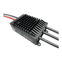
The YGE 205HVT Speedcontroller with BEC 12A/30A is a high-performance electronic speed controller designed for various RC applications, including helicopters, airplanes, and gliders. It offers a comprehensive set of features for precise motor control, battery management, and system integration.

Function Description:

The primary function of the YGE 205HVT is to regulate the speed of a brushless motor in an RC model. It achieves this through electronic speed control (ESC) with various operating modes tailored for different applications. The integrated Battery Eliminator Circuit (BEC) provides regulated power to the receiver and servos, eliminating the need for a separate receiver battery. The controller also incorporates advanced features like governor modes for consistent RPM in helicopters, active free-wheel for improved efficiency, and various protection mechanisms. Telemetry capabilities allow for real-time monitoring of critical parameters, enhancing safety and performance.

Important Technical Specifications:

  • Battery Compatibility: 4 to 14S LiPo (with undervoltage protection by power reduction) or 5 to 16S LiFePo4 (with undervoltage protection by power reduction).
  • BEC Output: 5.0V - 8.4V, 12A continuous, 30A peak.
  • Current Rating: Maximum continuous full power current as specified.
  • Dimensions: Approximately 84 x 56 x 31 mm.
  • Weight: Approximately 219g (without wires) / 287g (with wires).
  • Cable Diameter: Battery / Motor: 6mm² / 6mm².
  • Speed Limit: 240,000 rpm (2-Poles).
  • Timing: Automatic or 6-step adjustable.
  • Brake: Adjustable EMK brake, F3A (Acro brake with infinitely adjustable force).
  • Protection Features: Current limiting, disconnectable undervoltage detection, temperature and overload warning, anti-flash.

Usage Features:

The YGE 205HVT offers a versatile range of usage features, primarily configured through its mode programming and PC-Tool interface.

Mode Programming:

The controller features six distinct operating modes, each optimized for specific applications:

  • Mode 1: V-Stabi - Gov (external Governor): Designed for use with external FBL (Flybarless) systems that provide their own governor function. The controller's RPM output is connected to the FBL system's RPM/telemetry input.
  • Mode 2: Standard Governor Mode: Allows direct use of the ESC's internal governor. Users can switch between different RPMs in flight, starting with at least 70% throttle.
  • Mode 3: Gov.-Store: This mode requires an initial "learning" phase where the motor parameters are learned at a high RPM (over 70%) with blades. After learning, the controller can be started at lower RPMs and allows in-flight RPM switching. The governor RPM regulator in Mode 2 and 3 starts from 50% throttle opening, and operating below this is not recommended for helicopters.
    • Recommended throttle openings: Hover (Low RPM) 60-70%, Standard 70-80%, 3D 80-90%.
    • If head speed is too high, a lower pinion or motor with less KV is suggested. For heavy scale helicopters, a higher throttle opening is recommended to prevent heat losses.
  • Mode 4: Electronic gliders with brake: Includes all parameters for electronic gliders with brake.
  • Mode 5: Airplanes without brake: Contains all parameters for airplanes without brake.
  • Mode 6: Airplanes with Acro-brake (F3A brake): Specifically designed for F3A competition airplanes with Acro-brake.

Start-up Sequence:

After connecting the main battery, the controller emits 3 descending beeps. The connected motor acts as a beeper, indicating the number of cells with a series of long (5 cells) and short (1 cell) beeps. If the transmitter is in the correct stop position, 4 ascending beeps confirm the controller is ready. If the motor rotates in the wrong direction, any two of the three motor wires can be swapped to reverse direction.

PC-Tool:

The optional USB-adapter allows for fine adjustment and selection of telemetry logs via a PC setup. While basic parameters are set automatically through mode programming, the PC-Tool is useful for telemetry settings and advanced configurations.

Autorotation (AR) and Bailout:

It is crucial not to switch off the motor completely (0%) during autorotation. For bailout, the motor needs low RPM (10-20% throttle opening) to prevent overloading the motor/ESC and ensure a safe spool-up. The motor must be switched off completely once the model is on the ground to deactivate soft-start and bailout.

BEC Voltage Adjustment:

The BEC voltage can be adjusted in 0.1V steps using the PC-Software. A buffer battery can be used without diodes. It's important to match the battery voltage to the BEC voltage to prevent damage. Recommended batteries include a 2S-LiPo for 8.0V BEC, or 4-cell NiMh/NiCd for 5.5V-6.0V BEC. The ESC must be powered up first before connecting the buffer battery to ensure proper telemetry function.

Telemetry:

The ESC sends various data via telemetry, including voltage, current, capacity, BEC-voltage, RPM, throttle percentage, PWM, BEC-temperature, warnings, and error messages. The specific data displayed depends on the receiver and transmitter used. The YGE-protocol supports various systems like Futaba, Spektrum, FrSky, Core, MSH Brain 2, and Spirit FBL.

Integration with Specific Systems:

  • Jeti ExBUS: Configure the receiver for ExBUS on E1 or E2, connect the telemetry cable, and set Jeti ExBUS in the PC-Software. ESC parameters can then be configured in the JetiBox menu.
  • Multiplex MSBv2: Select MSBV2 as telemetry protocol in the PC-software to change or disable telemetry data addresses.
  • Graupner HoTT V4: Select HoTT V4 as telemetry protocol in the PC-software. ESC parameters can be configured in the transmitter's telemetry menu. Max PWM is shown as max. BEC-Temp due to limited data volume.
  • Mikado Vbar Control with NEO: Auto-detects and sets all parameters, including telemetry, without mode programming or PC-Setup. The YGE-App must be installed in VBC. This does not apply to older Vbars.

Maintenance Features:

  • Connections: Use clean and tight gold connectors (5.5mm or 6mm recommended) for motor and battery to ensure high current flow and prevent voltage peaks. The total wire length from controller to battery should not exceed 30cm; longer wires require additional low ESR capacitors (e.g., YGE Cap's 9 module). Motor cables can be longer but should be twisted to minimize interference.
  • Interference Prevention: Use the attached ferrite ring for both BEC cables to prevent interferences.
  • Cooling: Ensure sufficient air intake and, more importantly, a larger air outtake to avoid heat accumulation. If repeated temperature warnings occur, improve cooling or reduce current (e.g., by using a smaller propeller or a battery with one less cell).
  • Error Analysis: The ESC features a yellow LED for status indication and a red LED for error analysis. Flashing sequences indicate specific errors:
    • 2 Beeps/flashes: Under-voltage identification
    • 3 Beeps/flashes: Temperature rise warning
    • 4 Beeps/flashes: Overcurrent
    • 5 Beeps/flashes: Receiver signals failed
    • 6 Beeps/flashes: Start-up failed
    • 7x flashes: BEC-overload Errors are automatically deleted after approximately 1 minute of successful operation.
  • Safety Precautions:
    • Always remove rotor blades for safety during programming.
    • Ensure no objects are within the propeller circle when connecting batteries.
    • Do not reuse damaged controllers (e.g., broken, damaged by polarity inversion, or humidity).
    • The ESC should only be powered by batteries, not power supplies.
    • Inverting battery polarity leads to severe damage and voids the warranty.

The YGE 205HVT is a robust and feature-rich speed controller designed to meet the demands of advanced RC enthusiasts, offering precise control, comprehensive protection, and extensive telemetry capabilities for a wide range of applications.

YGE 205HVT Specifications

General IconGeneral
BrandYGE
Model205HVT
CategoryController
LanguageEnglish