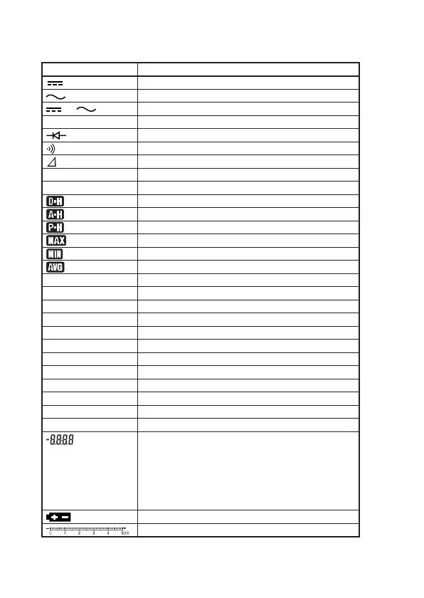
19
Appears when in DC-mode measurement
Appears when in AC-mode measurement
Appears when in DC+AC-mode measurement
Appears when the polarity is negative
Appears when in diode test
Appears when in continuity check
Relative calculation indicator
Fixed ranges indicator
AUTO range indicator
DATA HOLD indicator
AUTO HOLD indicator
PEAK HOLD indicator
Lit when in MIN/MAX/AVG-mode
Lit when in MIN/MAX/AVG-mode
Lit when in MIN/MAX/AVG-mode
Auto power off indicator
Unit for capacitance measurement
Unit for voltage measurement
Unit for current measurement
Unit for resistance measurement
Unit for temperature measurement
Unit for frequency measurement
Decibel calculation indicator
Unit for percentage calculation
Unit for duty cycle ratio calculation
Unit for voltage measurement (dB
V
, Hz
V
)
Unit for recording time when in MIN/MAX/AVG-mode
Recording time indicator when in MIN/MAX/AVG-mode
Number of saved data indicator
Reference value indicator when relative calculation
Duty cycle ratio indicator
Voltage value (dB
V
, Hz
V
) indicator
Reference resistance value (dBm) indicator
Appears when the batteries become low
Bar graph indicator, Range indicator
R•H
AUTO
AUTO OFF
nF, µF, mF
mV, V
µA, mA, A
MΩ, kΩ, Ω
˚C (˚F)
kHz, Hz
dB, dBm
% (Main-display)
% (Sub- display)
mV, V
(Sub- display)
s (Sub- display)
(Sub- display)
Symbol and Unit Description
+
–
 Loading...