Do you have a question about the Yolin YL90T-V and is the answer not in the manual?
Lists the various features of the YL90T display for riding needs, including indicators and settings.
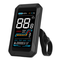
Details the distribution of functional areas on the YL90T display interface.
Defines the functions of the five buttons on the YL90T display's operating unit.
Explains how to power the YL90T display on and off, noting low leakage current when off.
Describes how to switch between different display interfaces like Odometer, Trip Odometer, Max Speed, and Average Speed.
Details how to engage and disengage the walk boost mode for the electric bicycle at a fixed speed.
Explains how to use the button to control the lights and adjust the display backlight brightness.
Guides users on how to adjust the Pedal Assist System (PAS) level to change motor output power.
Illustrates the 5-bar battery level indicator and explains what flashing bars signify.
Explains that the display shows error codes for faults and refers to Schedule 1 for definitions.
Explains how to set the display units to metric or imperial (P1).
Details how to set the rated voltage (P2) for the electric bicycle system.
Describes how to set the Pedal Assist System (PAS) levels (P3) from a range of options.
Explains how to adjust the PAS level ratio value (e.g., 01-50) to customize speed per level.
Details how to set the wheel diameter (P4) in inches for accurate speed and distance readings.
Explains how to set the number of speed sensor magnets (P5) based on the protocol used.
Guides on setting the maximum speed limit (P6) for the electric bicycle.
Details how to set the controller current limit (P7) to manage power output.
Configuration for PAS sensor settings.
Explains how to set the PAS sensor direction to front (run-F) or opposite (run-b).
Details how to adjust the PAS sensor sensitivity (SCN) from level 2 (highest) to 9 (lowest).
Explains how to set the number of pedal assist sensor magnets (PR5) within a specific range.
Configuration for throttle settings.
Details how to enable or disable the 6KM/H walk boost feature when using the throttle.
Explains how to enable or disable the throttle level (HF-Y/HF-N) affecting max speed.
Guides on activating and setting a four-digit power-on password (PA) for the display.
Explains how to set the auto sleep time (Pb) for the display to turn off when not in use.
Details the procedure to restore the display to its factory default settings.
Explains how to manually reset the trip odometer, noting the odometer cannot be reset.
Provides information about the limited warranty offered by Yolin for product defects.
Lists exclusions from the warranty coverage, such as physical damage or misuse.
Shows the standard wire connection sequence for controller and display connectors.