UNIT PLACEMENT
1. Provide a base in the pre-determined location.
2. Remove the shipping carton and inspect for possible dam-
age.
3. Compressor tie-down bolts should remain tightened.
4. Position the unit on the base provided.
5. Sit unit on the (4) rubber elevating grommets provided with
the unit. These should be positioned as shown in Figures
1 and 2 to reduce noise and allow for proper drainage.
6. Make a hole(s) in the structure wall large enough to accom-
modate the insulated vapor line, the liquid line and the
wiring.
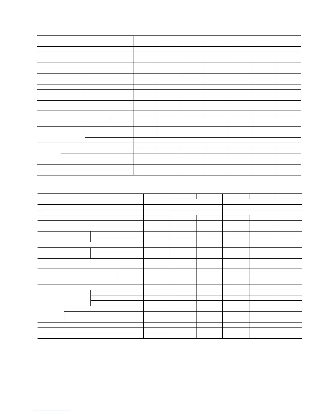
MODEL
E*FD
018 024 030 036 042 048 060
UNIT SUPPLY VOLTAGE 208/230-1-60
NORMAL VOLTAGE RANGE
1
187 to 252
MIN. CIRCUIT AMPACITY 12.3 15.3 19.3 23.2 27.2 33.1 36.1
MAX. OVERCURRENT DEVICE AMPS
2
20 25 30 35 40 50 60
COMPRESSOR TYPE Recip. Recip. Inertia Inertia Inertia Scroll Scroll
COMPRESSOR AMPS
RATED LOAD 9.2 11.6 14.8 17.3 20.5 25.2 27.6
LOCKED ROTOR 48 60 73 94 120 131 170
CRANKCASE HEATER
YES YES YES YES YES NO NO
FAN MOTOR AMPS
RATED LOAD 0.8 0.8 0.8 1.6 1.6 1.6 1.6
LOCKED ROTOR 1.9 1.9 1.9 3.8 3.5 3.5 3.5
MIN. FIELD WIRE SIZE AWG
60°C COPPER CONDUCTORS
14 12 12 10 10 8 8
MAX. WIRE LENGTH FEET BASED
ON 3% VOLTAGE DROP
208V 81 99 81 108 108 138 124
230V 90 110 90 120 120 153 138
FAN DIAMETER INCHES 18 18 18 18 24 24 24
FAN MOTOR
RATED HP 1/8 1/8 1/8 1/4 1/4 1/4 1/4
NOMINAL RPM 1075 1075 1075 1075 860 860 860
NOMINAL CFM
2000 2000 2000 2200 3200 3200 3300
COIL
FACE AREA SQ. FT. 14.2 15.1 15.1 17.0 20 20 24
ROWS DEEP 1 1 1 1 1 1 2
FIN / INCH 13 18 18 20 13 16 13
LIQUID LINE OD
3/8 3/8 3/8 3/8 3/8 3/8 3/8
VAPOR LINE OD 5/8 5/8 3/4 3/4 7/8 7/8 7/8
OPERATING WEIGHT LBS. 140 149 149 167 225 210 312
1
Utilization range “A” in accordance with ARI standard 110.
2
Dual element fuses or HACR circuit breaker. * May be 1 or 9.
TABLE 2 - PHYSICAL / ELECTRICAL DATA
MODEL
E1FD036 E1FD048 E1FD060 E1FD036 E1FD048 E1FD060
25 46
UNIT SUPPLY VOLTAGE 208/230-3-60 460-3-60
NORMAL VOLTAGE RANGE
1
187 to 253 432 to 504
MIN. CIRCUIT AMPACITY
15.2 20.1 21.4 8.0 9.0 10.1
MAX. OVERCURRENT DEVICE AMPS
2
25 30 40 15 15 20
COMPRESSOR TYPE Inertia Scroll Scroll Inertia Scroll Scroll
COMPRESSOR AMPS
RATED LOAD 10.9 14.8 15.8 5.8 6.5 7.4
LOCKED ROTOR
78 91 124 40 46 59.6
CRANKCASE HEATER YES NO NO YES NO NO
FAN MOTOR AMPS
RATED LOAD 1.6 1.6 1.6 0.8 0.8 0.8
LOCKED ROTOR 3.5 3.5 3.5 1.8 2.0 2.0
MIN. FIELD WIRE SIZE AWG
60°C COPPER CONDUCTORS
12 10 10 14 14 14
MAX. WIRE LENGTH FEET BASED ON
3% VOLTAGE DROP
208V 106 135 117 - - -
230V 117 150 130 - - -
460V - - - 261 240 200
FAN DIAMETER INCHES 18 24 24 18 24 24
FAN MOTOR
RATED HP 1/4 1/4 1/4 1/4 1/4 1/4
NOMINAL RPM 1075 860 860 1075 860 860
NOMINAL CFM 2200 3200 3300 2200 3200 3300
COIL
FACE AREA SQ. FT. 17 20 24 17 20 24
ROWS DEEP 1 1 2 1 1 2
FIN / INCH 20 16 13 20 16 13
LIQUID LINE OD 3/8 3/8 3/8 3/8 3/8 3/8
VAPOR LINE OD 3/4 7/8 7/8 3/4 7/8 7/8
OPERATING WEIGHT LBS. 167 210 312 167 210 312
1
Utilization range “A” in accordance with ARI standard 110.
2
Dual element fuses or HACR circuit breaker.
TABLE 3 - PHYSICAL / ELECTRICAL DATA
515.26-N5Y
Unitary Products Group 3
 Loading...