Stub kits are available to field fabricate quick connect line sets
or to connect mix-matched units and coils.
Unit should be installed only with approved system combina-
tions (indoor coil/outdoor unit) specified in Technical Guide.
See Application Data,"General Piping Recommendations and
Refrigerant Line Length," for vapor and liquid line sizing, cal-
culation of liquid line pressure loss or gain, determination of
vapor line velocity, elevation limitations, orifice corrections,
system charging, traps, etc.
Total line lengths are limited to 75 feet due to the storage
capacity of the accumulator. Systems with total line lengths
over 50 feet must be provided with a low voltage start kit.
Elevation differences are limited to:
Indoor Above Outdoor........50 ft.
Outdoor Above Indoor........50 ft.
Systems with liquid line pressure loss or gain greater than 11
psi must be provided with corrected orifice size.
Inter-connecting refrigerant lines should be sized to match the
factory supplied fittings. Liquid lines must
NEVER be increased
or decreased. Vapor lines
may be increased one size to mini-
mize pressure drop as long as a velocity of at least 1000 feet
per minute is maintained.
Additional charge is required for inter-connecting piping greater
than 15 feet for sweat units and some indoor coil matches.
The lines should be installed so that they will not obstruct
service access to the coil, air handling system or filter. Install
the lines with as few bends as possible. Care must be taken
not to damage the couplings or kink the tubing. Care must also
be used to isolate the refrigerant lines to minimize noise
transmission from the equipment to the structure.
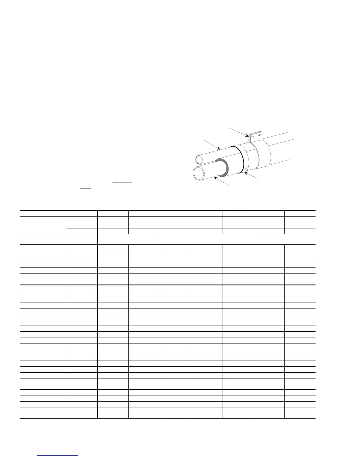
Tape and suspend the refrigerant lines as shown. DO NOT
allow metal-to-metal contact.
OUTDOOR UNIT E1FD / E9FD
018 024 030 036 042 048 060
UNIT ORIFICE(S)
1
55, 57 59, 61 67, 69 75 81 84, 87 99
FACTORY R-22
CHARGE, LBS. OZ.
SWEAT 4 - 11 5 - 15 6 - 6 6 - 9 7 - 6 7 - 9 15 - 5
QUICK 4 - 1 5 - 6 5 - 11 5 - 15 6 - 12 6 - 15 14 - 10
INDOOR COIL
COIL
ORIFICE2
SYSTEM ORIFICE + ADDITIONAL CHARGE, OZ.
G3HC / G1FC018 55 55 + 2 59 + 0 - - - - -
G3HC / G1FC024 61 57 + 14 59 + 0 - - - - -
G3HC / G1FC030 69 61 + 16 69 + 0 - - - -
G3HC / G1FC036 81 - - 69 + 4 75 + 0 - - -
G3HC / G1FC042 78 - - - 75 + 13 81 + 3 - -
G3HC / G1FC048 90 ----81 + 1184 + 0-
G3HC / G1FC060 96 -----87 + 1999 + 0
G3US018 55 55 + 2 59 + 0 - - - - -
G3UA024 59 55 + 14 59 + 0 - - - - -
G3UA030 65 - 61 + 16 - - - - -
G3UA036 69 - 61 + 16 69 + 4 75 + 0 - - -
G3UA037 69 - 61 + 16 69 + 4 75 + 0 - - -
G3UA048 87 ----81 + 1184 + 0-
G3UA060 96 -----87 + 1999 + 0
G3UA061 96 -----87 + 1999 + 0
G2UT024 - - + 0 - - - - -
G2UT030 - - +16 - - - - -
G2UT036 - - +16 +4 +0 - - -
G2UT037 - - +16 +4 +0 - - -
G2UT048 - ----+ 11+ 0-
G2UT060 - -----+ 19-
G2UT061 - -----+ 19+ 0
G3CN030 65 57 + 14 61 + 16 69 + 0 - - - -
G3CN042 73 - - - 75 + 13 81 + 3 - -
G3CN060 87 -----87 + 1999 + 0
F1RP / F1FP018 53 55 + 0 - - - - - -
F1RP / F1FP024 61 57 + 6 61 + 0 - - - - -
F1RP / F1FP030 65 - 61 + 0 67 + 2 - - - -
F1RP / F1FP036 75 - - - 75 + 0 - - -
F1RP / F1FP042 78 - - - 75 + 2 78 + 0 - -
1
These orfices are packed in the instruction/warranty packet of each outdoor unit.
2
These orifices are factory-mounted in the flow control device of each indoor coil.
NOTE: Orifices in ( ) must be ordered from the Parts Department.
TABLE 4- ADDITIONAL R-22 CHARGE/ORIFICE SIZE
LIQUID
LINE
TAPE
SHEET
METAL
HANGER
INSULATED
VAPOR LINE
FIGURE 6 - TUBING HANGER
515.26-N5Y
6 Unitary Products Group
 Loading...