292278-UIM-A-0108
28 Unitary Products Group
NOTES:
1. Airflow expressed in standard cubic feet per minute (CFM) and in cubic meters per minute (m
3
/min).
2. Return air is through side opposite motor (left side).
3. In order to stay within the velocity rating the filters, airflows above 1800 CFM (50.97 m
3
/min) require either return from two sides or one side plus bottom.
4. Motor voltage at 115V.
FILTER PERFORMANCE
The airflow capacity data published in Table 16 represents blower per-
formance WITHOUT filters. To determine the approximate blower per-
formance of the system, apply the filter drop value for the filter being
used or select an appropriate value from the Table 17.
NOTE: The filter pressure drop values in Table 17 are typical values for
the type of filter listed and should only be used as a guideline. Actual
pressure drop ratings for each filter type vary between filter manufactur-
ers.
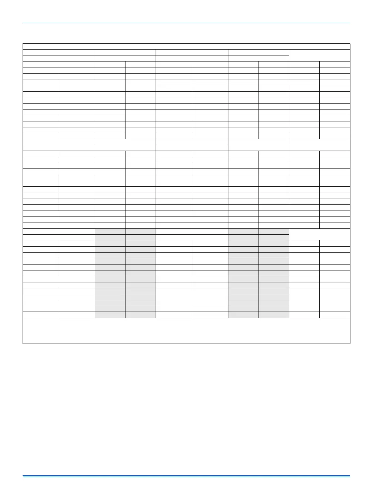
TABLE 16:
Air Flow Data
HIGH / LOW SPEED COOLING AND HEAT PUMP CFM
60,000 INPUT - 3 Ton 80,000 INPUT - 3 Ton 60,000 INPUT - 3 Ton 80,000 INPUT - 3 Ton
JUMPER SETTINGS
CFM CFM m³/min m³/min
High Low High Low High Low High Low COOL Tap ADJ Tap
1330 900 1310 890 37.7 25.5 37.1 25.2 A B
1130 800 1100 740 32.0 22.7 31.2 21.0 B B
1220 850 1220 830 34.6 24.1 34.6 23.5 A A
1040 730 1000 670 29.4 20.7 28.3 19.0 B A
1120 770 1090 720 31.7 21.8 30.9 20.4 A C
920 650 900 610 26.1 18.4 25.5 17.3 C B
950 660 880 610 26.9 18.7 24.1 17.3 B C
740 540 680 510 21.0 15.3 19.3 14.4 D B
860 610 810 580 24.4 17.3 22.9 16.4 C A
690 540 630 500 19.5 15.3 17.8 14.2 D A
790 570 730 530 22.4 16.1 20.7 15.0 C C
630 530 590 500 17.8 15.0 16.7 14.2 D C
80,000/100,000 INPUT - 4 Ton 100,000 INPUT - 5 Ton 80,000/100,000 INPUT - 4 Ton 100,000 INPUT - 5 Ton
JUMPER SETTINGS
CFM CFM m³/min m³/min
High Low High Low High Low High Low COOL Tap ADJ Tap
1660 1110 2210 1480 47.0 31.4 62.6 41.9 A B
1550 1050 1780 1180 43.9 29.7 50.4 33.4 B B
1610 1070 2040 1350 45.6 30.3 57.8 38.2 A A
1440 960 1620 1050 40.8 27.2 45.9 29.7 B A
1470 990 1840 1250 41.6 28.0 52.1 35.4 A C
1370 920 1560 1010 38.8 26.1 44.2 28.6 C B
1290 850 1470 940 36.5 24.1 41.6 26.6 B C
1130 790 1370 890 32.0 22.4 38.8 25.2 D B
1230 850 1460 930 34.8 24.1 41.3 26.3 C A
1050 720 1250 790 29.7 20.4 35.4 22.4 D A
1110 760 1310 810 31.4 21.5 37.1 22.9 C C
950 660 1090 690 26.9 18.7 30.9 19.5 D C
120,000 INPUT - 5 Ton
120,000 INPUT - 5 Ton
JUMPER SETTINGS
CFM
m³/min
High Low High Low COOL Tap ADJ Tap
2280 1510
64.6 42.8 AB
1860 1190
52.7 33.7 BB
2090 1370
59.2 38.8 AA
1630 1060
46.2 30.0 BA
1880 1250
53.2 35.4 AC
1620 1030
45.9 29.2 CB
1500 960
42.5 27.2 BC
1410 880
39.9 24.9 DB
1490 920
42.2 26.1 CA
1290 790
36.5 22.4 DA
1360 840
38.5 23.8 CC
1140 690
32.3 19.5 DC
All CFM’s are shown at 0.5” w.c. external static pressure.These units have variable speed motors that automatically adjust to provide constant CFM from 0.0” to 0.6” w.c. static
pressure. From 0.6” to 1.0” static pressure, CFM is reduced by 2% per 0.1” increase in static. Operation on duct systems with greater than 1.0” w.c. external static pressure is not
recommended.
NOTE: At some settings, LOW COOL airflow may be lower that what is required to operate an airflow switch on certain models of electronic air cleaners. Consult the instructions
for the electronic air cleaner for further details.
 Loading...