This document is an Installation and Maintenance Manual for YORK Floor Ceiling Air Conditioners, covering both R-410A 50Hz Heat Pump and R-410A 50Hz Cooling Only models.
Function Description
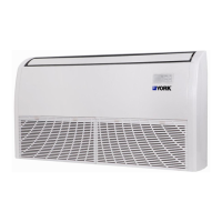
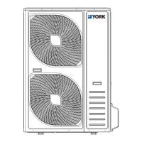
The YORK Floor Ceiling Air Conditioner is designed to provide comfortable room conditions by either cooling or heating the indoor environment. It operates by circulating refrigerant between an indoor unit and an outdoor unit. The system includes features for temperature control, fan speed adjustment, and various operational modes. The indoor unit is designed for either ceiling or floor standing installation, offering flexibility in placement. The outdoor unit houses the compressor and heat exchanger, facilitating the heat exchange process with the external environment.
Important Technical Specifications
The manual lists specific models and their corresponding refrigerant types and frequencies:
- R-410A 50Hz Heat Pump Models:
- YFKN18BZNREUH1
- YFKN24BZNREUH1
- YFKN36BZNREUH1
- YFKN42BZMREUH1
- YFKN48BZMREUH1
- YFKN55BZMREUH1
- R-410A 50Hz Cooling Only Models:
- YFJN18BZNRETH1
- YFJN24BZNRETH1
- YFJN36BZNRETH1
- YFJN42BZMRETH1
- YFJN48BZMRETH1
- YFJN55BZMRETH1
Outdoor Operating Temperature Range:
- Cooling Operation: Maximum 48°C, Minimum -15°C
- Heating Operation (Heat Pump): Maximum 24°C, Minimum -15°C
Storage Conditions:
- Temperature: -25°C to 60°C
- Humidity: 30% to 80%
Refrigerant Piping and Electrical Wiring:
The manual provides detailed diagrams for refrigerant flow and electrical wiring, differentiating between 18K/24K/36K models and 42K/48K/55K models for electrical connections.
- Pipe Diameter (Gas Pipe / Liquid Pipe / Drain Pipe) and Torque (Nm) for Flare Nuts:
- 18K (18,000 Btu/h): Gas Φ12.7, Liquid Φ6.35, Drain De25. Torque: Φ6.35mm (20 Nm), Φ9.52mm (40 Nm), Φ12.7mm (60 Nm), Φ15.88mm (80 Nm), Φ19.05mm (100 Nm).
- 24K (24,000 Btu/h): Gas Φ15.88, Liquid Φ9.52, Drain De25.
- 36K, 42K, 48K, 55K (36,000-55,000 Btu/h): Gas Φ19.05, Liquid Φ9.52, Drain De25.
- Maximum Tube Length (L) and Height Difference (H) for Outdoor Unit Installation:
- 18K: Max. L 30m, Max. H 15m. Additional refrigerant: 15g/m (exceeding 5m).
- 24K/36K/42K/48K/55K: Max. L 50m, Max. H 30m. Additional refrigerant: 35g/m (exceeding 5m).
- Electrical Specifications (ELB - Earth Leakage Breaker):
- 18K (220-240V~, 50Hz): Nominal Current 20A, Nominal Sensitive Current 30mA. Power Source Cable Size 3×2.5mm², Transmitting Cable Size 4×1.5mm².
- 24K (220-240V, 50Hz): Nominal Current 32A, Nominal Sensitive Current 30mA. Power Source Cable Size 3×2.5mm², Transmitting Cable Size 4×1.5mm².
- 36K (220-240V~, 50Hz): Nominal Current 40A, Nominal Sensitive Current 30mA. Power Source Cable Size 3×4.0mm², Transmitting Cable Size 4×1.5mm².
- 42K/48K/55K (380-415V 3N~, 50Hz): Nominal Current 32A, Nominal Sensitive Current 30mA. Power Source Cable Size 5×2.5mm², Transmitting Cable Size 4×1.5mm².
- Note: Max. Running Current (A) refers to the nameplate. Wire sizes are minimums and should comply with EN60335-1. For transmitting cable lengths over 15 meters, a larger wire size is recommended.
Usage Features
- Control: The unit can be controlled via an optional wired remote controller (JCSA21NEWH) or a wireless remote controller (JCRA31NEWH). These controllers manage power ON/OFF, operating mode, temperature, and fan speed.
- Display Panel: The indoor unit features a display panel with indicators for:
- Filter Clean (Yellow): Lights up when the filter needs cleaning.
- Defrost (Green): Lights up during defrosting, turns off when complete.
- Timer (Green): Lights up when the timer is activated, turns off when the timer is off.
- Run (Red): Lights up during operation, turns off in SLEEP mode.
- Infrared Receiver: Receives signals from the wireless remote controller.
- Emergency Switch: Resets the filter clean indicator. A short press stops operation; a press for more than 5 seconds initiates cooling mode.
- Operation Modes: Includes Cooling and Heating operations.
- Special Remarks:
- 3 Minutes Protection: Compressor remains off for at least 3 minutes after stopping to protect it.
- 5 Minutes Protection: Compressor runs for at least 5 minutes once started.
- Cooling Operation: Indoor fan runs continuously.
- Heating Operation: Capacity depends on outdoor temperature. Cold air prevention feature delays indoor fan operation until the heat exchanger reaches a certain temperature.
- Anti-freezing Function (Cooling): Unit switches to fan mode if indoor outlet air temperature is too low to prevent frost/ice formation.
- Defrosting: Operates when outdoor temperature is low to remove frost/ice from the outdoor heat exchanger, reducing heating performance. Indoor fan may stop or run at low speed during defrosting.
- Residual Heating Air: Fan runs at low speed after stopping heating to blow out residual warm air.
- Auto Re-start: Unit resumes previous settings after a power break.
- Air Flow: The indoor unit features an Air Intake, Filter (inside Air Intake), Display Panel, Air Outlet, Vertical Louver (inside Horizontal Louver), and Horizontal Louver. Vertical adjustment louver swing is automatic on some models.
Maintenance Features
- Safety Notices: Emphasizes installation by qualified technicians, proper electrical work, use of specified parts, solid base for installation, dedicated power circuits, correct wiring, and proper earth connection. Warns against using flammable gases, inadequate drain piping, and overtightening flare nuts.
- Troubleshooting: Provides guidance for common issues:
- No Cooling/Heating: Check for airflow obstruction, heating sources, clogged air filter, open doors/windows, or operation outside temperature range.
- Abnormal Smells: Clean air filter and panels, ensure good ventilation.
- Deforming Parts Sound: Normal during system start/stop due to thermal deformation.
- Steam from Outdoor Heat Exchanger: Normal during defrosting.
- Dew on Air Panel: Can occur under high humidity during prolonged cooling.
- Refrigerant Flow Sound: Normal during system start/stop.
- If Trouble Remains: Contact installer with unit model name and trouble description.
- No Operation: Check SET TEMP.
- Filter Cleaning: Instructions for removing and installing the air filter from the air return grille are provided, including sliding holding knobs and removing screws.
- Air Purging and Test Run:
- Air Purging with Vacuum Pump: Detailed steps for connecting a vacuum pump to remove air and moisture from the refrigerant system, ensuring pressure is below 15Pa (1.5×10⁻² bar) for 5 minutes.
- Leak Test: Use liquid soap to check all joints and valves for leaks.
- Tidying Up Piping: Insulate joints, straighten and fix connecting tubes to the wall, seal wall holes.
- Test Run: Conduct according to the manual, ensuring power and unit run well, and testing Cooling, Dehumidifying, and Heating modes.
- Electrical Installation: Requires an ELB (Electric Leakage Breaker) and checks for insulation resistance (more than 2MΩ) and fully opened stop valves before operation. Specifies cable sizes for power source and transmitting cables.
- Disposal: The product is marked for correct disposal within the EU, indicating it should not be treated as household waste but recycled responsibly through designated collection systems or retailers.