Do you have a question about the York ZT078-102 and is the answer not in the manual?
Discusses safety alerts and hazard types like DANGER, WARNING, CAUTION.
Procedures for checking unit for damage during transit.
Lists available related technical documents and guides.
Lists CSA certifications for the unit.
General safety rules to follow before installation.
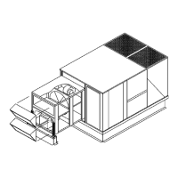
Initial steps to prepare the unit for installation.
Guidelines for selecting a suitable installation site for the unit.
Procedures and precautions for moving and lifting the unit.
Diagram of left/end duct connection dimensions.
Diagram of the unit's roof curb dimensions.
Design and sizing recommendations for ductwork.
Information on using side panels for economizer hoods.
Instructions for installing the condensate drain connection.
Information on compressor type and oil requirements.
Details on filter installation and maintenance.
Guidelines for field wiring and electrical safety.
Recommendations for thermostat installation and wiring.
Diagram showing typical control wiring connections.
Information on factory-installed electric heaters.
Details on gas-fired heating systems.
Guidelines for proper gas pipe sizing.
Table of minimum supply air for gas heating.
Procedures for routing and connecting the gas supply line.
Specific recommendations for gas piping installation.
Requirements for LP gas systems.
Details on factory-installed smoke detector operation and limitations.
Information on factory or field-installed outdoor dampers.
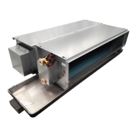
Details on economizer options and installation.
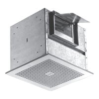
Information on power exhaust options.
Details on VFD installation and parameter configuration.
Explains the operation of the manual bypass switch for VFD.
Overview of economizer operational modes.
Describes various minimum position sequences.
How low ambient conditions affect economizer operation.
How air monitoring affects economizer reset.
Details on demand ventilation operation.
Discusses different free cooling selection methods.
Describes thermostat sequences for CV option A.
Details single enthalpy economizer operation.
Details dual enthalpy economizer operation.
Describes thermostat sequences for CV option B.
Operation for CV option A in occupied mode.
Operation for CV option B in occupied mode.
Operation for unoccupied modes.
Operation details for VAV unit sensor option A.
Operation details for VAV unit sensor option B.
How economizer loading functions.
Setpoints, inputs, and outputs for power exhaust.
Description of analog inputs on the economizer board.
Further description of analog inputs.
Description of LEDs on the economizer board.
Description of SA Bus connections.
Description of analog outputs on the economizer board.
Description of binary outputs.
Description of 24V IN connections.
Description of binary inputs.
Details on indoor air quality sensing.
Instructions for checking compressor and blower rotation.
How to check blower rotation.
Steps for adjusting belt tension.
Explains corrections for altitude and temperature.
Steps to select the correct drive.
Table for RPM selection.
Details on motor, sheaves, and belts for blower.
Table of power exhaust motor specs.
Balancing supply and return air in conditioned space.
Methods to measure airflow.
General overview of unit operation.
Step-by-step process for cooling operation.
How economizer provides free cooling.
Describes errors related to cooling system operation.
How the unit operates in low ambient conditions.
Monitors safety inputs like limit switches and pressure sensors.
Inherent protection features for compressors.
Details the MagnaDRY reheat mode sequence.
Step-by-step process for normal cooling mode.
Describes alternate mode operation.
Diagram for cooling operation circuit.
Diagram for reheat operation circuit.
Details on the optional aux mode for reheat.
Describes how electric heat operates.
Details errors related to electric heat.
How the temperature limit affects blower operation.
Safety controls for electric heat units.
Function of the auxiliary limit switch.
Step-by-step for gas heating ignition.
How flame sensing works.
Monitoring of the gas valve.
Safety controls for gas heat units.
Settings for gas heat anticipators.
Checklist before and after cooling start-up.
Checklist before gas heating start-up.
Procedure for lighting the main burners.
Checks after heating section operation.
How to check gas heat input.
Procedure to measure gas flow for second stage.
Procedure to measure gas flow for first stage.
How to adjust gas manifold pressure.
Table of gas heat stages and input.
How to adjust temperature rise.
Procedures for inspecting and servicing burners and orifices.
Details on thermostat connection points.
Details on limit, power, and shutdown connections.
Details on space temperature sensor connections.
Details on temperature sensor connections.
Further details on temperature sensor connections.
Details on pinned connections.
Details on heat section connections.
Details on cooling and fan output pins.
Details on safety switches and overloads.
Details on SA BUS connections.
Information on the unit's user interface.
Description of UCB LEDs.
Details on optional communication sub-boards.
Recommended cables for FC and SA buses.
Table of ignition control flash codes and their meanings.
Instructions for charging the unit by weight or table.
Charging data for ZT078 system 1.
Charging data for ZT090 system 1.
Charging data for ZT090 system 2.
Charging data for ZT102 system 1.
Charging data for ZT102 system 2.
Charging data for ZT120 system 1.
Charging data for ZT120 system 2.
Charging data for ZT150 system 1.
Charging data for ZT150 system 2.
General safety precautions for start-up procedures.
Fields for specifying engineering application data.
Section for recording air flow measurements.
Section for recording electrical data.
Section for recording cooling measurements.
Checks for refrigerant system safety.
Section for recording gas heating measurements.
Verifying staging control operations.
Final checks before concluding the start-up process.
Area to document any issues found.