EasyManua.ls Logo

YOSE POWER DZ40 - User Manual

YOSE POWER DZ40
12 pages
Print Icon
To Next Page IconTo Next Page
Loading...
DZ40 display
Specification Manual
Product Name: LCD Display
Product Model: DZ40
Question and Answer IconNeed help?

Do you have a question about the YOSE POWER DZ40 and is the answer not in the manual?

Summary

Product Introduction

Product Name and Model

Identifies the product as LCD Display, model DZ40.

Product Introduction Details

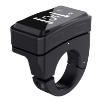
Highlights features like slim design, high brightness, waterproof rating (IP65), and UART interface.

Scope of Use

Specifies compatibility with EN15194 electric bicycles.

Appearance and Size

Details housing materials (ABS, PC) and provides dimensional drawings.

Display Coding Rules

Explains the structure and meaning of product model codes and serial numbers.

Product Description

Specification Parameters

Lists power supply, rated current, leakage current, display type, communication mode, and operating temperatures.

Function Overview

Outlines key features: button operation, speed display, gear control, battery indication, walk-assist, and fault codes.

Installation Method

Describes how to mount the display on the handlebar and connect it to the controller.

Display Interface

Details the icons and information shown on the display during startup and riding.

Key Definition

Defines the function of each button (M, Λ, V) on the display unit.

Function Operation

Explains how to turn on/off, switch assist gears, use walk-assist, and control headlights.

Electricity Display

Describes how battery power is indicated and provides a voltage correspondence table.

User Settings

Covers settings for unit, wheel diameter, speed limit, and battery voltage.

Fault Information

Explains fault icon display and provides definitions and analysis for fault code E30.

Wiring Definition

Details the standard connector pinout and wire color functions for connecting the display.

Important Attention

Overview

The DZ40 is an LCD display designed for EN15194 electric bicycles. It features a simple and thin design, intended for installation on the left handlebar, and can be used in conjunction with a middle display. The display utilizes a high-brightness white nixie tube for clear visibility.

Function Description:

The DZ40 display provides essential information and control for electric bicycle operation. Key functions include:

  • Speed Display: Shows real-time speed.
  • Gear Control: Allows control over 0-5 gears, with a default setting of 0-5.
  • Battery Indication: Features a six-level battery indicator, showing levels 1-5 and providing an under-voltage prompt (indicated by one light flashing).
  • Walk-Assist Function: Enables a walk-assist mode.
  • Headlight Indication: Displays the headlight status (requires controller support).
  • Fault Code Indication: Shows fault codes to help diagnose issues.
  • User Settings: Allows users to adjust various parameters, including unit settings (metric KM/imperial MI), wheel diameter information, and speed limit information. Battery voltage is a fixed display item.

Important Technical Specifications:

  • Power Supply: DC 24V/36V/48V.
  • Rated Current: 18mA/36V.
  • Shutdown Leakage Current: < 1uA.
  • Display Type: White digital tube display.
  • Communication Mode: UART (default).
  • Working Temperature: -20°C ~ 60°C.
  • Storage Temperature: -30°C ~ 80°C.
  • Waterproof Level: IP65.
  • Housing Material: ABS.
  • Upper Housing Window Material: Brown PC with high hardness.
  • Installation: Designed for standard handle pipe size φ 22.2, fixed with an M3 inner hexagon screw. Locking torque is 0.8N.m.

Usage Features:

  • Four Buttons: The display is equipped with four buttons for easy operation: a switch on/off button, a function key, an adjustment key+ (for the upper part of the display area), and an adjustment key- (for the lower part of the display area).
  • Power On/Off: To turn on, press the switch on/off key for 2 seconds when the display is off. To turn off, long-press the switch on/off key for 2 seconds in the power-on state. The display automatically turns off after 5 minutes of inactivity (if speed is 0).
  • Power Shift Switching: Press the adjustment key+ or adjustment key- to switch between assist gears (0/low/medium/high).
  • Assist Implementation: Press and hold the adjustment key- button for 2 seconds to enter boosting state; release it to exit.
  • Headlight Control: Press and hold the function key for 1 second to turn on headlights (if supported by the controller), which also dims the display. Press again for 1 second to turn off headlights and restore display brightness.
  • User Settings Access: Within 10 seconds of startup, press and hold the function key for 2 seconds to enter the user setting interface. Long-press the function key for 2 seconds to exit and save settings. If no operation occurs for 10 seconds in the setting interface, the display reverts to normal riding state without saving.
  • Unit Setting: Allows switching between metric (KM) and imperial (MI) units. The factory default is KM.
  • Wheel Diameter Information: Users can view wheel diameter information (e.g., 700C, 27.5).
  • Speed Limit Information: Displays the speed limit (default is 25 km/h).
  • Battery Voltage Check: Shows the collected battery voltage (two digits, decimal places rounded off).
  • Battery Display: When battery power is normal, a 5-segment LCD displays power, and the outer frame lights up. When exhausted, the 5-segment LCD is extinguished, and the outer frame flashes, indicating immediate charging is needed.

Maintenance Features:

  • UART Communication Interface: Provides a convenient interface for maintenance services.
  • Fault Code Display: The display shows a fault icon and flashing fault code (e.g., E30 for communication failure) to help identify issues.
  • Fault Code Definition: The device defines ERROR 30 for communication failure, which means the display cannot receive data from the controller or receives incorrect data.
  • Troubleshooting for E30:
    1. Check if TX and RX communication lines are connected correctly.
    2. Check if the harness and connector are loose or broken.
    3. Verify if the display communication protocol matches.
  • Wiring Definition: A standard connector wiring definition table is provided, detailing the function of each line (Red: VCC, Blue: Kp, Black: GND, Green: RX, Yellow: TX). Note that for waterproof plug-ins, lead colors may not be visible in the harness.

General Attention Points:

  • Always ensure safety during use.
  • Do not plug or unplug the display while the power supply is active.
  • Avoid using the device in harsh environments such as heavy rain, heavy snow, or direct exposure.
  • If the display cannot be used normally, it should be repaired as soon as possible.

YOSE POWER DZ40 Specifications

General IconGeneral
BrandYOSE POWER
ModelDZ40
CategoryMonitor
LanguageEnglish