2
Isolation withstanding voltage : Between power, relay contact or signal terminal ≥2300VDC;
Between SSR voltage output and thermocouple input
≥600VDC
Power supply : 100~240VAC, -15%, +10% / 50Hz; 120~240VDC; or 5VA.
Operating Ambient : temperature (-10~60) ; humidity ≤90%RH℃
3. Rear Terminal Layout and Wiring
This is wiring graph for E5, and ALM is an optional alarm
module.
In AI-7048 size E5(DIN rail), E(48X96)mm, F(96X48)mm
and A(96X96)mm, those size can have the alarm action
output after installed the following modules:
L1 : Relay output module (2A/240VAC, NO+NC)
L5 : Dual relay output module (2A/240VAC, NO), can
change to NC by mode by change the parameter “ nonc”
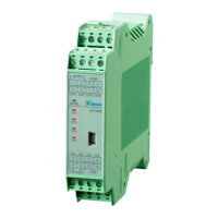
The wiring layout of D5 size. (22.5 X 100)mm, DIN rail.
D5 size no dry contact alarm output.
Terminal 1 and 2:
Power supply of 100~240VAC 50Hz or 24VAC/DC.
Terminal 9-12:
The positive poles of thermocouple inputs of channel 1-4;
Terminal 15 and 16
:
The common
Negative pole of thermocouple inputs and can be free connected.
Terminal 5-8
:
The positive poles of SSR voltage outputs of channel 1-4
Terminal 3-4
:
The common
Negative pole of SSR voltage outputs, and be free connected. The SSR voltage outputs is
12-16VDC/20mA with protection for short circuit.
Terminal 13 and 14
:
RS485 communication.
“MODE” LED: indicate the status of communication and alarm.
COMM
OP3
COM
LM
COMM
L2
1
2
3
4
5
6
7
8
9
10
11
12
15
16
17
18
19
20
13
14
L1
OP4
+
+
B
100-240VAC~
+
+
COM
COM
N/O N/O
N/O
N/C
+
+
CJC
OP2
OP1
IN4
IN3
IN2
IN1
O P 3 O P 4O P 1 O P 2
IN 4
IN 3IN 2IN 1
1 41 3
R S 4 8 5
A
B
9 1 0
1 61 5
C O M -
1 21 1
O P 4
O P 1
O P 3
O P 2
M O D E
21
5 6
1 0 0 - 2 4 0
V A C ~
43
87
C O M -

 Loading...