EasyManua.ls Logo

Yudo TW 600 User Manual

Yudo TW 600
8 pages
To Next Page IconTo Next Page
Page #1 background imageLoading...
Page #1 background image
HEAD OFFICE & FACTORY
169-4, Gujang-Ri, Paltan-Myun, Hwasung-City, Gyeonggi-Do, 445-915 Korea
Tel : + 82 31 350 2530 (Overseas Sales Team) Fax : + 82 31 354 7446
E-Mail : yudo@yudohot.com Website : www.yudo.com
We reserve the right to change specifications without notice.
Ver. 1.5 MN TW 600 (11. Sep)
MODEL : TW 600
User Manual
TW 600
SEQUENCE INJECTION TIMER
www.yudo.com
English
Question and Answer IconNeed help?

Do you have a question about the Yudo TW 600 and is the answer not in the manual?

Yudo TW 600 Specifications

General IconGeneral
BrandYudo
ModelTW 600
CategoryTimer
LanguageEnglish

Summary

Introduction and Product Overview

Product Uses and Benefits

Highlights benefits like weld line control, injection quantity regulation, and flash/short-shot improvement.

Power Supply Specifications

Details AC/DC input voltages, signal input power, solenoid valve output, and operating temperature.

TW 600 Components and Configuration

TW 600 Parts Identification

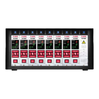
Identifies key components like delay and open time settings, LEDs, and control keys.

Solenoid Valve Output Power

Specifies the output voltage display for solenoid valves.

Operational Functions and Settings

Main Power Input Operation

Explains the startup sequence, version display, and self-inspection process.

Mode and Time Setting Procedures

Details how to change operating modes and set delay/open times.

Time Setting Adjustments

Covers specific methods for setting delay and open times across different modes.

Solenoid Output Voltage Configuration

Guides on setting the correct output voltage for solenoid valves.

Advanced Mode Operations and Applications

Mode A Operation Details

Gate opens after delay and stays open until the injection signal ends.

Mode B Operation Details

Gate opens after delay for a set duration, then closes.

Mode C Operation Details

Enables sequential Mode B operations for complex timing requirements.

Injection Signal Extension Function

Allows the gate to remain open even after the injection signal has ended.

System Integration and Wiring

Sequence System Application Examples

Illustrates applications for Mode A, B, and C in various injection scenarios.

Connector Assembly and Pinout

Details the connector pin assignments for solenoid valve connections.

Sequence Timer Connection Diagram

Solenoid Valve Control Overview

Visualizes the control flow from the timer to solenoid valves.

Global Sales and Service Network

Related product manuals