Do you have a question about the Yudo TCT-8P and is the answer not in the manual?
Details main power, signal input, and solenoid valve output power.
Describes the structure of the control and display PCBs.
Identifies S.M.P.S, M.P.U, and RELAY functions.
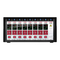
Illustrates the YUDO control panel with indicators and buttons.
Explains the purpose of SET, Color Change, OPEN, navigation, OK, and ON/Off buttons.
Describes gate status LEDs, mode LEDs, output voltage, and signal LEDs.
Details the DC24V/AC220V output for each gate.
Guides on connecting power, signal, and output cables.
Explains the power LED and initial display of timing values.
How to switch modes and save settings.
Details output modes (constant/pulse) and frequency settings.
Instructions for opening all gates or specific gates manually.
Procedures for setting DEL and OPEN times for gates.
Describes the timing sequence for Mode A operation.
Illustrates Mode A operation with various injection signal conditions.
Explains Mode B timing and provides operational examples.
System behavior when injection signals cease during operation.
Explains output voltage and input status indicators.
Precise timing and operational descriptions for Mode A and B.
Visual examples of gate opening patterns for different modes.
Practical applications of Mode A in molding processes.
Practical applications of Mode B in molding processes.
Specifies voltage and current ratings for all connections.
Instructions for connecting main power and signal inputs.
Guides on connecting solenoid valves to gate outputs.
Procedure for selecting the output voltage via jumper settings.