CLM920_AC3 Module Hardware Usage Guide
Shanghai Yuge Information Technology co., LTD
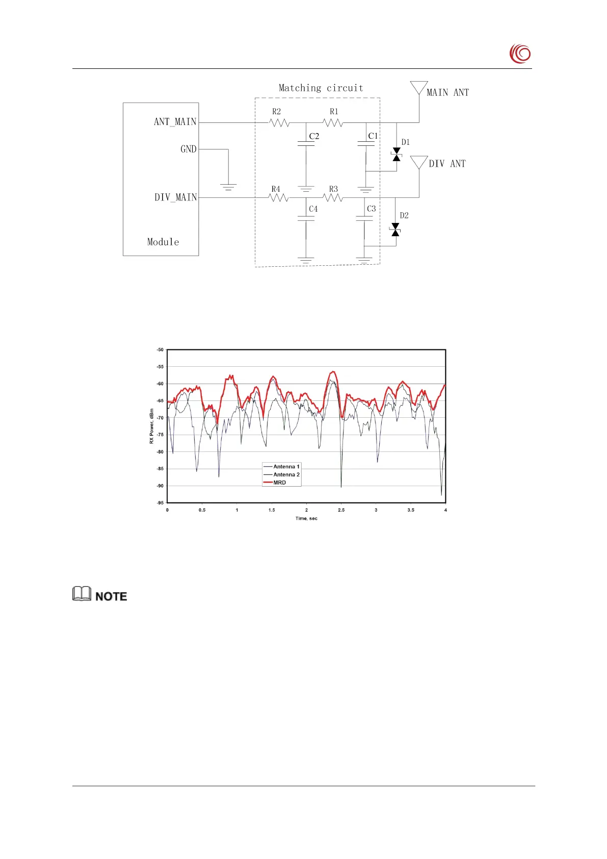
Figure 3-23 Antenna matching circuit
Figure 3-24 Comparison of received signal strengths with and without diversity antennas
The CLM920 AC3 module provides two RF antenna interfaces, which are the main set
antenna and the diversity antenna respectively. The antenna interface must be a 50 ohm
characteristic impedance trace.
The main antenna and the diversity antenna are distributed reasonably to improve the
In actual use, the antenna board can be debugged and optimized according to the user's
circuit board. The motherboard R1/R2/R3/R4 defaults to 33pF, and C1/C2/C3/C4
defaults to empty. During this period, it is recommended to attach a bidirectional TVS


 To Next Page