Do you have a question about the YZ Systems NJEX 8300G and is the answer not in the manual?
Explains how to use the NJEX-8300 Operations Manual effectively.
Provides contact information and guidance for obtaining assistance with the 8300 system.
Details the conventions used in the manual for readability and clarity.
Lists the key operational parameters and specifications for the 8300 system.
Explains the fundamental working principles of the 8300 system and its components.
Details optional components and accessories available for the NJEX system.
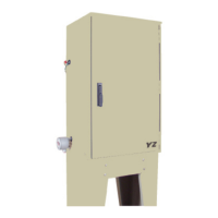
Lists and describes the primary components of the standard NJEX-8300G system.
Illustrates the schematic of the NJEX 8300 system, showing component flow paths.
Provides instructions and specifications for mounting the system enclosure.
Details the required field connections for operating the 8300G system.
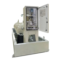
Lists and describes the primary components of the NJEX SkidMount Series.
Describes the function and location of the bulk odorant filter.
Explains the cable connecting system control and mechanical sections.
Describes the expansion tank's role in pressure regulation.
Details the NJEX gas filter and its function.
Explains the actuation gas regulator's function.
Describes the purpose of the service tray.
Illustrates the schematic of the NJEX 8300 system, showing component flow paths.
Provides dimensions and mounting recommendations for skid systems.
Details field connections for skid-mounted NJEX 8300G systems.
Step-by-step guide for the initial filling of the bulk odorant tank.
Provides instructions for refilling the bulk odorant tank.
Introduces the control/electronics system and its main components.
Explains the function and operation of the N-300 controller keypad.
Details the procedure for powering up the N-300G controller and system.
Explains the functionality of the Test and Standby keys on the N-300G controller.
Describes the battery and solar panel components and their function.
Outlines the methods for communicating information from the N-300 controller.
Discusses communication configuration options for the 8300 system.
Details how to set essential operational parameters for Proportional-to-Flow mode.
Continues the explanation of setting operator input parameters for Proportional-to-Flow.
Continues the explanation of setting operator input parameters for Proportional-to-Flow.
Continues the explanation of setting operator input parameters for Proportional-to-Flow.
Continues the explanation of setting operator input parameters for Proportional-to-Flow.
Continues the explanation of setting operator input parameters for Proportional-to-Flow.
Details Modbus communication parameters for system configuration.
Details how to set operational parameters for Proportional-to-Time mode.
Continues setting operator input parameters for Proportional-to-Time mode.
Continues setting operator input parameters for Proportional-to-Time mode.
Continues setting operator input parameters for Proportional-to-Time mode.
Explains setting the Modbus address for the odorizer.
Details Modbus communication parameters for system configuration.
Continues setting operator input parameters for Proportional-to-Time mode.
Guides calibration of analog flow inputs (voltage or current).
Continues calibration of analog flow inputs.
Details zero calibration for the expansion tank pressure transmitter.
Guides zero calibration for the odorant inlet pressure transmitter.
Guides calibration for pulse flow inputs (dry contact, voltage pulse).
Explains how to calculate pulse input frequency for calibration.
Provides a method to calculate span frequency for calibration.
Explains how the display changes to indicate system conditions.
Guides on how to view real-time operational data on the N-300 controller.
Explains the 'Strokes Signaled' display.
Explains the 'Odorant Injected' display.
Explains the 'Pump Displacement' display.
Lists conditions causing pump alarm indications.
Describes the Verometer level display and automatic refill function.
Lists 12 alarm and non-alarm indicators for Verometer operation.
Lists non-alarm indicators related to Verometer operation.
Continues detailing how to view real-time data on the N-300 controller.
Describes the expansion tank pressure display.
Describes the odorant inlet pressure display.
Explains the battery voltage display and alarm.
Explains the flow input display and associated alarms.
Lists alarms related to the flow input.
Lists non-alarm indicators for flow input.
Describes the odorant supply level display in the bulk tank.
Details alarms for low and high odorant tank levels.
Describes the display of odorant temperature, time, and date.
Configures which alarms activate the alarm output contact.
Continues configuring alarm output status for various system components.
Guides on testing alarm outputs and simulating system alarms.
Continues instructions for testing alarm outputs and simulating alarms.
Continues instructions for testing alarm outputs and simulating alarms.
Details how to set the internal clock and date on the N-300G controller.
Continues instructions for setting the internal clock and date.
Introduces the mechanical system and its main components.
Describes the odorant inlet manifold and bulk odorant filter.
Explains the purpose and operation of the fill valve.
Details the purpose and function of the Verometer as an odorant meter.
Describes the Model 8000 pump, its actuation, and displacement.
Details the odorant discharge manifold and its connections.
Describes the NJEX gas filter and its function.
Describes the solenoid valves and pneumatic relay manifold.
Describes the expansion tank's role as a pressure buffer.
Details how to set system pressures and verify valve positions.
Guides testing and adjustment of the low pressure relief.
Provides a step-by-step guide to starting the NJEX system.
Details the procedure for stopping the NJEX system pump.
Outlines a schedule for preventative maintenance tasks.
Lists recommended maintenance tasks by inspection frequency.
Lists recommended spare parts for the NJEX system.
Guides the inspection of the overflow protector assembly.
Guides testing and adjustment of the low pressure relief.
Provides instructions for performing a forward purge procedure.
Provides instructions for venting pressure gas from the system.
Provides instructions for filling the Verometer.
Guides on priming and starting the NJEX system.
Explains how to use the troubleshooting section effectively.
Provides contact information for further technical assistance.
Lists crucial safety precautions for maintenance.
Outlines the recommended order for resolving issues.
Addresses alarms related to the odorant tank level.
Continues troubleshooting for tank level alarms.
Provides steps to troubleshoot tank level alarms.
Explains the low battery alarm condition.
Provides steps to troubleshoot battery alarms.
Describes signal alarms (loss of signal, overflow).
Describes non-alarm indicators for signal issues (low flow, no flow).
Provides steps to troubleshoot signal alarms and indicators.
Continues troubleshooting for signal alarms and indicators.
Lists Verometer alarms and their descriptions.
Steps to troubleshoot Verometer cable communication issues.
Steps to troubleshoot Verometer 'No Fill' alarms.
Continues troubleshooting steps for Verometer 'No Fill' alarms.
Steps to troubleshoot Verometer 'Slow Fill' alarms.
Steps to troubleshoot Verometer 'Leakage' alarms.
Steps to troubleshoot Verometer 'Fill Valve Failure' alarms.
Steps to troubleshoot Verometer 'Odorant Inlet Cable' alarms.
Steps to troubleshoot Verometer 'Odorant Inlet Low' alarms.
Steps to troubleshoot Verometer 'Odorant Inlet Hi' alarms.
Steps to troubleshoot Verometer 'Expansion Tank Cable' alarms.
Steps to troubleshoot Verometer 'Expansion Tank Low' alarms.
Steps to troubleshoot Verometer 'Expansion Tank High' alarms.
Steps to troubleshoot Verometer 'Overfill' non-alarm indicators.
Steps to troubleshoot Verometer 'Fill Rate' non-alarm indicators.
Lists pump alarms and their descriptions.
Continues troubleshooting for Verometer 'Expansion Tank High' alarms.
Steps to troubleshoot 'Pump Over Pumping' alarms.
Steps to troubleshoot 'Pump Under Pumping' alarms.
Steps to troubleshoot 'Pump Failure' alarms.
Continues troubleshooting steps for 'Pump Failure' alarms.
Shows an assembled view of the NJEX Model 8000 Pump.
Provides an exploded view of the NJEX Model 8000 Pump Actuation Assembly.
Shows an exploded view of pump diaphragm and C.V. cartridges.
Provides an exploded view of the Fill Valve assembly.
Shows an exploded view of the VM-2100 Verometer and filter assembly.
Illustrates the components of the Bulk Odorant Filter.
Shows the components of the NJEX Gas Filter.
Illustrates the Back Pressure Regulator and its ports.
Shows the NJEX system's Electronics Assembly.
Illustrates the SPS-12 Solar Power Supply Unit.
Illustrates the LPS-120/240 Charger Supply Unit.
Details communication settings for Modbus protocol.
Lists supported Modbus functions for the N300 controller.
Describes Boolean data types and their Modbus usage.
Lists Modbus control functions for the N300 controller.
Continues discussion of Boolean registers and their Modbus functions.
Lists Modbus status functions and their descriptions.
Lists Modbus alarm functions and their descriptions.
Describes integer data types and their manipulation via Modbus.
Lists Modbus registers for result data functions.
Lists Modbus registers for parameter functions.
Lists Modbus exception codes and their meanings.
Continues listing Modbus registers for parameter functions.
Provides a form to record initial NJEX 8300 setup information.
Fields for basic system information for record-keeping.
Fields for location-specific information.
Fields to record system operating conditions.
Fields to record system operational parameters.
Section to select and record the system's run mode.
Provides a diagram illustrating the N-300 Controller display menus.
Notes and recommendations for system installation.
Details field connections for ATEX system configurations.
| Model | NJEX 8300G |
|---|---|
| Category | Industrial Equipment |
| Manufacturer | YZ Systems |
| Features | robust construction |
| Benefits | reduced downtime |
| Description | High-performance industrial extruder designed for demanding applications requiring precision and reliability. |