MOBILE APP Z
-
WAVE.ME
ANTENNA
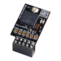
1. The connector sits on pins 1-10
onthe Raspberry Pi
2. Duplicate connector
3. Two LEDs for operation indication
4. U.FL connector for external antenna
connection
SHIELD DESCRIPTION
2
1
3
4
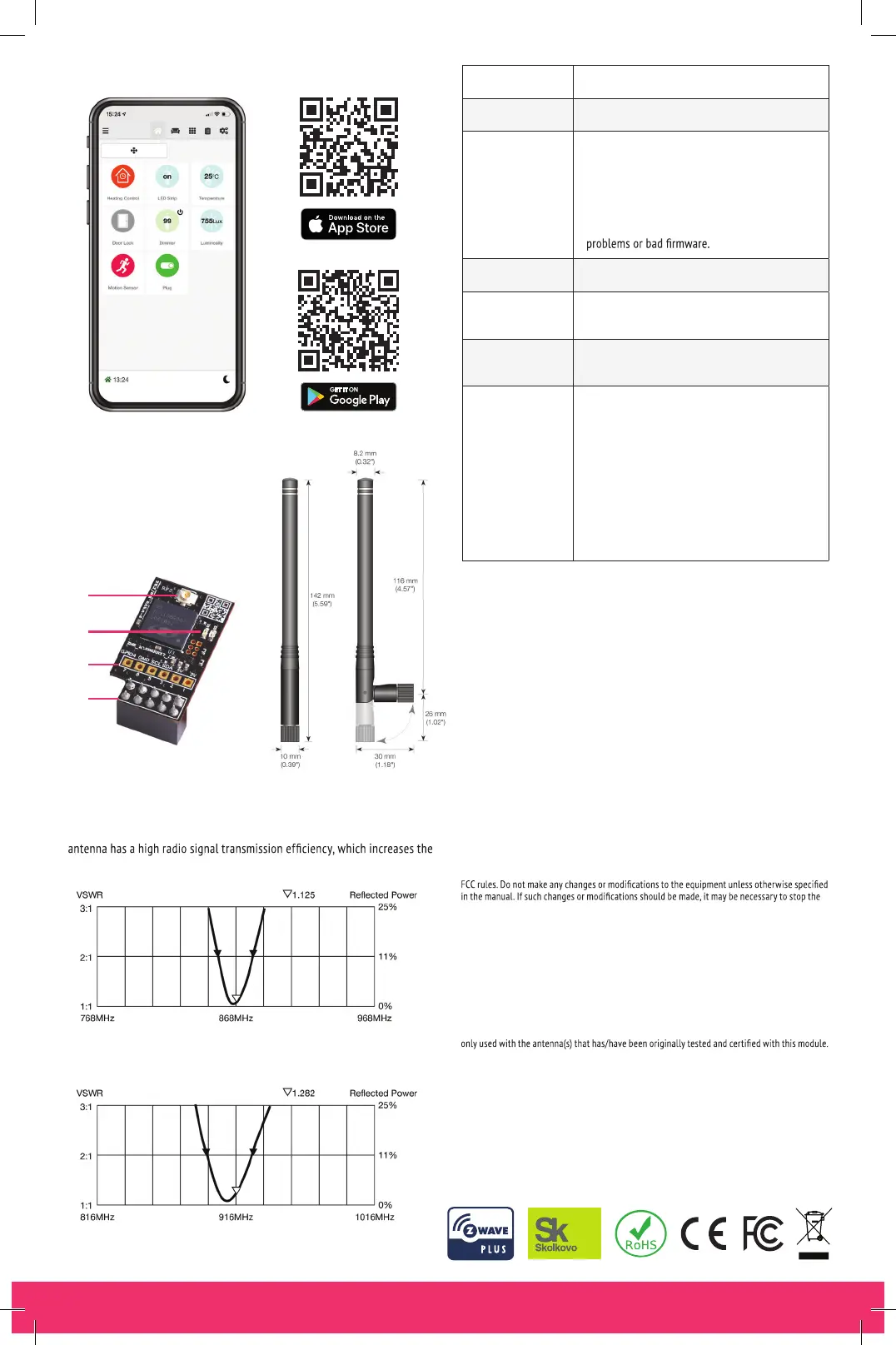
The kit includes a 100 mm Linx SMA coaxial cable with a U.FL connector and
a Linx antenna with a base that can rotate to 360° and tilt to 90°. The Linx
range of the radio communication.
Z-Wave Transceiver Silicon Labs ZGM130S
Wireless Range Min. 40 m indoor in direct line of sight
Self-Test
When powering on, both LEDs must shine for
about 2 seconds and then go off. If they don’t,
the device is defective.
If the LEDs do not shine for 2 seconds: hardware
problem.
If the LEDs are faintly shining constantly: hardware
Dimensions/Weight 30 x 17 x 12 mm / 16 gr
LED indication
Red: Inclusion and Exclusion Mode
Green: Send Data.
Interface
TTL UART (3.3 V) compatible with Raspberry Pi
GPIO pins
Frequency range
ZMEERAZBERRY7_ANT: (865...869 MHz):
Europe (EU), India (IN), Russia (RU) [default],
China (CN), South Africa (EU), Middle East (EU)
ZMEURAZBERRY7_ANT: (908...917 MHz):
America, excluding Brazil and Peru (US) [default],
Israel (IL)
(919...921 MHz): Australia / New Zealand /
Brazil / Peru (ANZ), Hong Kong (HK), Japan (JP),
Taiwan (TW), Korea (KR)
The Linx ANT-916-CW-HWR-SMA antenna is used
for908...917, 919...921 MHz (ZMEURAZBERRY7_ANT)
The Linx ANT-868-CW-HWR-SMA antenna is used
for 865...869 MHz (ZMEERAZBERRY7_ANT)
FCC STATEMENT
FCC Device ID: ALIB2-ZMERAZBERRY7ANT
This device complies with Part 15 of the FCC Rules. Operation is subject to the following two
conditions:
(1) This device may not cause harmful interference, and
(2) This device must accept any interference received, including interference that may cause
undesired operation.
NOTE: This equipment has been tested and found to comply with the limits for Class B digital
devices, pursuant to Part 15 of the FCC rules. These limits are de
signed
to provide reasonable
protection against harmful interference in a residential installation. This equipment generates,
uses and can radiate radio frequency energy and, if not installed and used in accordance with
the instructions, may cause harmful interference to radio communications. However, there is
no guarantee that interference will not occur in aparticular installation. If this equipment does
cause harmful interference to radio or television reception, which can be determined by t
urning
thee
quipment off and on, the user is encouraged to try to correct the interference by one or more
of the following measures:
1. Reorient or relocate the receiving antenna.
2. Increase the distance between the equipment and the receiver.
3. Connect the equipment into an outlet on a different circuit to which the receiver isconnected.
4. Consult the dealer or an experienced radio/TV technician for assistance.
Use of the shielded cable is required to comply with Class B limits in Subpart B of
Part 15 of the
operation of the equipment.
NOTE: If static electricity or electromagnetism causes data transfer to discontinue midway (fail),
restart theapplication or disconnect and connect the communication cable (USB, etc.) again.
Radiation Exposure Statement: This equipment complies with the set out FCC radiation
exposure limits for anuncontrolled environment.
Co-location warning: This transmitter must not be co-located or operated in conjunction with
any other antenna or transmi
tter.
OEM inte
gration instructions: This module has a LIMITED MODULAR APPROVAL, and is intended
only for OEM integrators under the following conditions: As a single, non-colocated transmitter,
this module has no restrictions in relation to a safe distance from any user. The module shall be
Aslong as these conditions above are met, further transmitter testing will not be required.
However, the OEM integrator is still responsible for testing their end-product for any additional
compliance requirements necessary for this installed module (for example, digital device
emissions, PC peripheral requirements, etc.).
 Loading...