Do you have a question about the Zanussi ZS12V70CCHI and is the answer not in the manual?
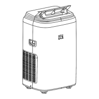
Provides dimensional and visual details of the indoor unit.
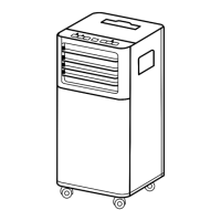
Presents dimensions and visual representation of the outdoor unit.
Electrical schematic for indoor units of 12K capacity.
Electrical schematic for indoor units of 18K and 24K capacities.
Electrical schematic diagram for the outdoor unit.
Identifies components and connectors on the indoor unit's PCB.
Identifies components and connectors on the PCB for 18K/24K units.
Identifies components and connectors on the outdoor unit PCB.
Illustrates the refrigerant flow for cooling and heating modes.
Guidelines for safe electrical installation and handling.
Safety measures and considerations for unit installation.
Safety procedures for handling and transporting the unit.
Details on how to connect various cables for the unit.
Wiring diagrams and specifications for electrical connections.
Specifications for piping length and vertical elevation limits.
Key information and notes for proper unit installation.
Step-by-step guide for installing the indoor unit.
Procedure for performing correct flaring work on pipes.
Steps for removing burrs from pipes to prevent leakage.
Instructions for placing nuts on pipes after burr removal.
How to connect tubing to the indoor unit's piping.
Procedure for connecting tubing to the outdoor unit.
How to form and secure piping with insulation and tape.
Steps to check the drainage system for proper function.
Procedure for installing electrical wires in the indoor unit.
Procedure for installing electrical wires in the outdoor unit.
Common uses and advantages of R-410A refrigerant.
Safety measures and potential hazards associated with R-410A.
Detailed steps for charging the system with R410A refrigerant.
Precautions and steps to take before cleaning the unit.
Instructions for cleaning the main body of the unit.
Procedure for cleaning the air filters for optimal cooling.
How to clean the air outlet louvers and the front panel.
Steps to prepare the unit for long periods of inactivity.
Key considerations for troubleshooting Zanussi inverter models.
Procedure for testing indoor unit component functionality.
General guidelines for handling malfunctions and error codes.
List of error codes, their meanings, and troubleshooting steps.
Codes indicating protection modes triggered by external factors.
Visual guides for diagnosing and resolving specific errors.
Protection mechanisms related to outdoor temperature limits.
Protection based on indoor unit evaporator temperature.
Protection related to fluctuations in AC voltage.
Protection based on outdoor unit condenser temperature.
Details on compressor types and winding resistance measurements.
Information on indoor unit fan motor types and specifications.
Steps to enter and use the remote control's setting mode.
Steps for disassembling the indoor unit, starting with filters and louvers.
Instructions for removing the front panel and case of the indoor unit.
Steps to remove the drain tray from the indoor unit.
Procedure for removing the electrical box assembly.
Steps to remove the evaporator from the indoor unit.
Instructions for removing the fan motor and cross fan.
Instructions for removing the big holder on the outdoor unit.
How to access and remove the valve cover.
Steps to remove the top panel of the outdoor unit.
Procedure for removing the front grille for access.
Instructions for removing the front panel of the outdoor unit.
Steps to remove the control unit and terminal block.
How to remove the reactor component.
Steps for removing the axial fan.
Instructions for removing the motor bracket and fan motor.
How to remove soundproof sponge material.
Steps to remove refrigerant components like the 4-way valve.
Procedure for removing the compressor from the unit.
Steps for removing the condenser unit.
| Brand | Zanussi |
|---|---|
| Model | ZS12V70CCHI |
| Category | Air Conditioner |
| Language | English |