This document provides technical directions for the overhaul of ZAVOLI GE, GES, GEX, and GEXL regulators/vaporizers, which are devices designed to convert gas from a liquid to a gaseous state and reduce operating pressure in CNG systems. The manual outlines detailed procedures for disassembling, replacing components, reassembling, and testing these regulators/vaporizers.
Function Description:
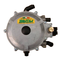
The ZAVOLI GE, GES, GEX, and GEXL regulators/vaporizers are critical components in Compressed Natural Gas (CNG) systems. Their primary function is to facilitate the phase change of CNG from its liquid state to a gaseous state, making it suitable for combustion in an engine. Concurrently, these devices reduce the high operating pressure of the CNG to a level appropriate for the engine's fuel system. The different models (GE, GES, GEX, GEXL) likely cater to various vehicle types or performance requirements, with the GEXL model potentially offering enhanced features such as a reinforced low-pressure lever cut-off.
Important Technical Specifications (derived from overhaul kits):
The overhaul kits for these regulators/vaporizers include a range of specific components, indicating their internal structure and the parts subject to wear and tear. Key components and their quantities in the kits are:
- 1st stage cut-off valve (1001C): 1 unit. This valve is crucial for the initial pressure reduction stage.
- 4x7.5 headless screw (threaded rod) (1003/1): 2 units. Used for securing internal components.
- 4x7.5 regular screw (1003/2): 4 units. General purpose screws for assembly.
- Low-pressure lever/electrovalve cut-off (10012C): 2 units for GE/GES/GEX, 1 unit for GEXL. This component is central to the second stage of pressure regulation. The GEXL kit also includes a "Reinforced low-pressure lever cut-off" (10012CR), suggesting a design improvement for durability or performance in that model.
- O-Rings:
- 5.28x1.78 O-Ring – plunger/idle channel screw top (10015B): 2 units.
- 12.42x1.78 O-Ring – electrovalve sleeve/register/channel (10021B): 2 units.
- 9.25x1.78 O-Ring – electrovalve screw top/bleed valve screw top (10025B): 2 units.
- 18.77x1.78 O-Ring – gas outlet connection (10030B): 1 unit.
- 10.82x1.78 O-Ring – water outlet connection (10031B): 4 units.
These O-rings are vital for sealing various connections and preventing leaks, highlighting the importance of maintaining airtight integrity within the regulator.
- Diaphragms:
- 1st stage diaphragm - “101GE” REGULATOR (101COM004): 1 unit.
- Full low-pressure diaphragm (100COM016): 1 unit.
Diaphragms are flexible membranes that respond to pressure changes, controlling the flow of gas through the different stages of the regulator. Their replacement is a key part of the overhaul process.
Usage Features:
The regulators/vaporizers are designed for integration into CNG systems. While the manual focuses on maintenance, the components listed (e.g., gas outlet connection, water inlet/outlet connections, electrovalve) indicate a standard design for such devices. The electrovalve suggests electronic control over gas flow, likely for precise regulation and safety. The presence of water inlet/outlet connections implies that the device uses engine coolant to heat the regulator, preventing freezing during the vaporization process of CNG.
Maintenance Features:
The manual is entirely dedicated to the overhaul process, emphasizing the importance of regular maintenance for these devices.
- Overhaul Kits: Specific kits (101K02 for GE, 100K02 for GES/GEX, 100K05 for GEXL) are provided, containing all necessary replacement parts. This streamlines the maintenance process and ensures compatibility.
- Cleaning: The main body of the regulator should be cleaned with a brush and a degreasing detergent to remove oil, grease, etc. Sandblasting or other abrasive tools are explicitly warned against, as they can damage critical components. Compressed air is recommended for proper cleaning.
- Component Replacement: Detailed instructions are provided for replacing key components:
- 1st stage lever cut-off: Involves removing the old rubber top and installing a new one.
- 2nd stage lever rubber top: Requires careful removal of the old rubber top, especially for GEXL models where a reinforced cut-off is used.
- Movable core cut-off of the electrovalve and O-Ring sleeve: Involves holding the sliding metallic component and carefully removing the rubber top.
- All O-Rings: Emphasizes caution to avoid damaging the seats during replacement. This includes O-rings for the separate idle register, sensitivity register, gas outlet connection, water outlet connection, electrovalve screw top, bleed valve screw top, and separate idle channel screw top.
- Reassembly: Step-by-step instructions for reassembling the regulator/vaporizer, including:
- Installation of cut-off valves: On both 1st and 2nd stage levers, using a punch and pliers respectively.
- Installation of electrovalve piston rubber top: Involves pressing and turning the piston clockwise.
- Installation of 1st and 2nd stage levers: Requires inserting pins and securing screws.
- Installation of high-pressure diaphragms: Crucially, the diaphragm hook must be properly fastened to the 1st stage lever to ensure correct regulator operation. A similar warning is given for the 2nd stage diaphragm.
- Installation of covers: 1st stage cover (fastened with 5.5 Nm torque wrench) and 2nd stage cover.
- Installation of bleed valve screw top and sensitivity register: For the sensitivity register, greasing the spring and placing it correctly on the "dot" is highlighted. For GEX and GEXL models, a stopper must be placed on the register spring, not on the "dot."
- Installation of gas outlet and water inlet/outlet connections: Involves inserting, twisting, and fastening with screws.
- Installation of electrovalve sleeve, separate idle channel screw top, electrovalve and screw top, and screw top: Specific torque (3 Nm) and wrench sizes (size 17 for electrovalve sleeve, size 3 hexagonal for idle channel screw top) are provided.
- Testing Procedures: After reassembly, the regulator must undergo testing to ensure proper function and leak-free operation.
- Required tools: A T-joint, a valve, a pressure gauge (min. 4-BAR), a 12-Volt power supply, CNG joints, and hoses.
- Connection to compressed air circuit: The regulator/vaporizer is connected to a compressed air circuit.
- Energizing the 12-Volt coil: This activates the electrovalve.
- Sensitivity register and separate idle check: These components must be tightly fastened, and air flow from the gas outlet connection should be checked. Slowly unscrewing them should result in increasing air flow.
- Final adjustment caution: After testing, both the sensitivity register and the separate idle must be slightly adjusted (about ½ turn for separate idle, and a variable turn for sensitivity register depending on vehicle type) to ensure proper starting.
- Leak check: Disconnecting the coil and compressed air, then re-energizing the coil after 3 minutes, should result in a small amount of air from the gas inlet connection if the electrovalve is working correctly and there are no leaks.
The detailed, step-by-step instructions, coupled with visual aids (figures), make this manual a comprehensive guide for technicians performing maintenance on ZAVOLI CNG regulators/vaporizers. The emphasis on correct assembly, torque specifications, and proper component placement underscores the precision required for these safety-critical devices.