ZEFTRONICS
Electrical Charging Systems Solutions
1622 E. Whaley St., Longview, TX 75601. USA
Ph: 903-758-6661; Fax: 903-236-9766. E-mail: Tech@zeftronics.com
Ph: 1-800-362-8985. Web Site
: www.zeftronics.com
R15100
14V ELECTRONIC ALTERNATOR CONTROLLER
By Femi G. Ibitayo
©2003, Z
EFTRONICS, Tovya Group Inc
R15100-PIT.pub. Pg 2/4
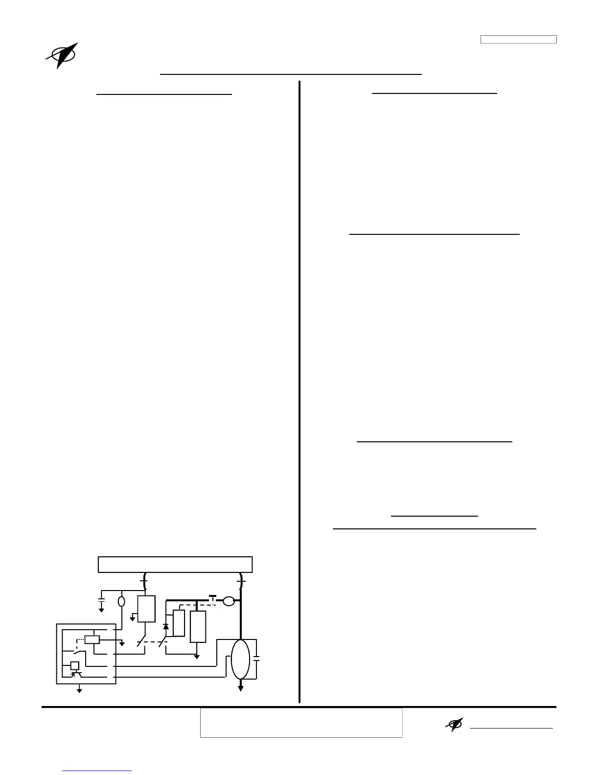
HOW THE SYSTEM WORKS
Closing the Bat switch applies the battery voltage to
pin A of the alternator controller (ACU, regulator).
With voltage at pin A (Alt switch off), the LV light
comes on, indicating that the alternator is off-line.
Closing the Alt switch applies battery voltage to pin S
through the Over Voltage Sensor (OVS). The OVS’
output controls a relay inside the alternator controller.
With power applied to pin S, that relay’s normally
open (NO) contacts connects pin A and pin I.
With power on pin S, current flows from the alterna-
tor’s Bat terminal through the controller’s voltage
regulator to the alternator’s field. The regulator keeps
the bus voltage constant (around 14V) by controlling
the alternator's field current. It increases the field
current with increase in system load and decreases it,
with a decrease in the system load.
Since the whole field current (max about 3.5 Amps)
flows from the alternator’s Bat terminal to pin A of
the controller, abnormal increases in wire, connection,
or junction resistances will cause poor voltage regula-
tion and or fluctuating charge meter, panel lights, and
bus voltage.
If the field of the alternator shorts to ground, the con-
troller will be damaged. To get field-to-ground short
protection update to the R15100 Rev A.
If the bus voltage exceeds about 16V, the Over Volt-
age Sensor (OVS) will open and thus remove power
from pin S. Removing power from pin S will turn off
the controller and take the alternator off line.
LV-OV Light
The LV-OV light on the instrument panel indicates
the condition of the charging system. See the trouble-
shooting section for how this function operates.
INSTALLATION INSTRUCTION
1. Disconnect and remove the present ACU/VR.
2. Measure the Alternator’s Field Resistance between
the field wire of airframe’s VR connector and
Ground. 3.5 to 6Ω is normal resistance. If is less than
3Ω or greater than 8Ω, check the alternator field or
the field wire for problems. 0Ω means Fld-Gnd short.
3. Check the ALT switch resistance: 0.1Ω is normal.
4. Mount and connect the new ACU to the system.
5. Perform the Post Installation Test Procedure.
POST INSTALLATION TEST PROCEDURE
1. With the engine off, turn on the Alt & Bat switches,
on the instrument panel, observe that the LV-OV
light is off. Verify that the voltage drop across the
alternator switch and 5 Amp circuit breaker is less
than 0.2V.
2. Verify that the voltage drop from the alternator BAT
terminal to pin A is less than 0.2V.
4. If the steps 1 to 3 are successful, perform steps 5 & 6.
5. Turn off all the avionics and any other voltage sensi-
tive devices.
6. Start the engine, and at 1500 RPM measure a bus
voltage of 13.9-14.4V. If the bus voltage exceed
these limits, check for voltage drops from the
alternator BAT terminal to pin A and wires/
connection from the ACU (F) to the alternator’s field.
TROUBLE-SHOOTING THE SYSTEM
For help on how to solve problems in the system, see the
Trouble-Shooting Notes (TSN) page and or TechCards.
I
NSTRUCTIONS FOR
C
ONTINUED AIRWORTHINESS MAINTENANCE
This device is not field repairable or serviceable. For all
service, repair or overhaul needs, return it to Z
EFTRON-
ICS
or a ZEFTRONICS approved repair station.
For all periodic inspection and test requirement, use the
pre and post installation procedure listed above.
Contact us with tech support questions that are not ad-
dressed at Zeftronics.com or in the TSN or TechCards.
B
60A
or X
A
Alt Fld BUS BAR Alt Out
ALT
F
LV-OV Light
2A
Alt
ACU
Relay
I
- BAT +
Bat Relay
Bat
A
F
VR
Red
OVS
Orange
S
ZEFTRONICS: SOLUTIONS
 Loading...