ZEFTRONICS
Electrical Charging Systems Solutions
1622 E. Whaley St., Longview, TX 75601. USA
Ph: 903-758-6661; Fax: 903-236-9766. E-mail: Tech@zeftronics.com
Ph: 1-800-362-8985. Web Site
: www.zeftronics.com
TROUBLE-SHOOTING THE SYSTEM
14V Type B alternator system on Beech, Cessna, Grumman, Maule etc
By Femi G. Ibitayo
©2003, Z
EFTRONICS, Tovya Group Inc
R15100-PIT.pub. Pg 3/4
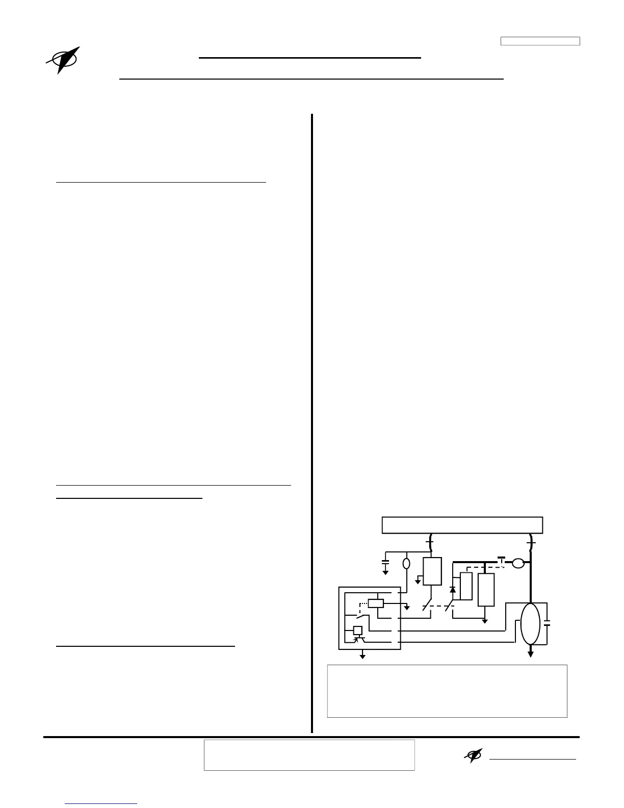
In this Type B system: the controller is between the
Bus and the Alt field. To control the bus voltage, the
unit switches power to one side of the field several
times a second. The OVP opens when OV occurs.
BETTER TROUBLE-SHOOTING TECHNIQUE
The most common trouble-shooting technique
involves replacing suspected defective parts until
problem goes away. That shot-gun method is a very
expensive and often unsuccessful. Using a more
systematic approach to trouble-shooting alerts the
user or mechanic to the conditions of the field circuit
breaker, alternator switch, alternator controller, and
alternator's field. This approach to trouble-shooting
looks at the condition of the pre-controller,
controller, and post-controller components.
PRE-CONTROLLER CONDITION: Check the
condition of the alternator switch, the field circuit
breaker, or the wiring from the Alt Bat to pin A on
the controller is open.
VOLTAGE REGULATOR CONDITION: Are the
voltages on pins I, A, S and F according to the
installation test data on page 4? If not, use the
information on these 4 pages to solve the problem.
ALTERNATOR FIELD CONDITION: Are the
field resistances measured from the airframe ACU
connector and at the alternator according to the
installation test data on page 4? If not, use the
information on these 4 pages to solve the problem
Most electrical charging system problems are easily
solved by applying the systematic trouble-shooting
approach with a good understanding of Ohm’s law
and basic electricity.
Check the condition of the ACU
1. With the master switch (Bat & Alt) on, at the
ACU connector, measure the indicated voltages.
Pin I: ______ Pin A: ______ Pin S: ______
Pin F:______ Bus ______
The voltages on pins I, A, S should equal bus’.
The voltage pin F should be 0.5-2V less than the
bus’. If the pin I voltage is less than bus voltage,
look for bad LV-OV light, broken wire from LV-
OV light, grounded pin I or damaged controller.
If the pin A voltage is less than bus’, look for
corrosion on the BAT terminal, socket for pin A
on the airframe ACU connector, or wire (from
ALT Bat to pin A) with high resistance. This may
cause fluctuating charge meter or bus voltage,
and may cause over-voltage and nuisance tripping
(i.e. alternator dropping off-line).
If the pin S voltage is less than bus’, look for a
grounded pin S or damaged controller. Pin S to
ground on the controller is about 400Ω.
If the pin F voltage is the same as the bus voltage,
look for a damaged or un-grounded controller. If
it is 0V, look for a grounded ALT field.
2. If the Master switch is a split type, turn off the
Alt Sw and measure the indicated voltages.
Pin I: ______ Pin A: ______ Pin S: ______
Pin F:______ Bus ______
The voltages on pins I, S & F should be 0-2V, pin A
should be battery or bus voltage.
If pin I has bus voltage on it, look for a short between
pins A & I (internal or external to the controller).
Disconnect the controller, a resistance of 0-1K
between pins A & I indicates a damaged controller.
Check the alternator Field & Power input wire
3. Disconnect/Remove the connector on the ACU.
Measure the resistance at the identified points.
Pin F to Gnd ______Ω. FLD to Gnd ______Ω
Pin A to ALT Bat _______Ω
The normal Alt field resistance is 3-6Ω.
A lower or higher resistance may indicate problems
with the alternator. Field resistance below 3Ω may
indicate a short to ground, while higher than 6Ω
dirty brushes or intermittently open field.
B
60A
or X
A
Alt Fld BUS BAR Alt Out
ALT
F
LV-OV Light
2A
Alt
ACU
Relay
I
- BAT +
Bat Relay
Bat
A
F
VR
Red
OVS
Orange
S
ZEFTRONICS: SOLUTIONS
 Loading...