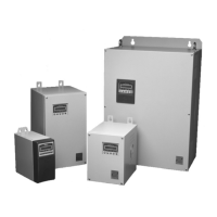
IM00094
10 January 2002
Introduction
This guide describes the installation, and operations of the
MSC-3 24Volt
option.
Specifications:
•
Galvanic isolation to +/- 42volts with respect to chassis earth.
•
24 Volts +/- 10% at 20 mA
•
Short circuit protected
Installation
WARNING!
The MSC3 under operation has hazardous internal voltages. Ensure all power sources are
removed for the duration of the Option Board installation. Allow at least 2 minutes for hazardous voltage
levels to discharge.
IP30 Chassis A Installation
1. Ensure all power sources have been removed for at least 2 minutes and that they remain that way for
the rest of the installation.
2. Remove the bottom section of the MSC3 blue plastic moulding to reveal the power terminals.
3. Remove the screw holding the control board/display assembly and pull it off the drive.
4. Turn the control board/display assembly over and plug the Option Board into one of the available option
connectors.
5. Lay the mylar insulation sheet on top off the exposed metal work and replace the control
board/display/option assembly.
6. Replace the original mounting screw and install the Option Board mounting screw. The Option Board is
ready for wiring as indicated at the option board terminal block.
7. Once wiring is complete replace the bottom moulding.
IP 66 Chassis A Installation and all other chassis
1. Ensure all power sources have been removed for at least 2 minutes and that they remain that way for
the rest of the installation.
2. Open the front door and remove the screws securing the control board to the chassis and lift of the
control board.
3. Turn the control board over and plug the Option Board into one of the available option connectors.
4. Lay the Mylar insulation sheet on top off the exposed metal work and replace the control board/option
assembly.
5. Replace the mounting screws. The Option Board is ready for wiring as indicated at the option board
terminal block.
6. Once wiring is complete close the front door.

 Loading...