EasyManua.ls Logo

Zenith H27F36DT Series User Manual

Zenith H27F36DT Series
62 pages
To Next Page IconTo Next Page
Page #1 background imageLoading...
Page #1 background image
SERVICE MANUALSERVICE MANUALSERVICE MANUAL
Product Type:
Chassis
Manual Series:
Manual Part #:
Model Line:
Product Year:
Model Series:
CONTENTS
General Information/Remote Controls................................
Installer ’s Menu ............................................................
Servicing/Trobleshooting ................................................
Model/Module Parts List .................................................
Exploded Views .............................................................
Schematics ...................................................................
Published by
Technical Publications
Zenith Electronics Corporation
P.O. Box 240007
Huntsville, Al 35824
Copyright May 2005 by Zenith Electronics Corporation ©
Printed in U.S.A.
Zenith
Commercial Color TV
CL
SR25
3828VD0171B
F
2005
1
2
3
4
5
6
H19F34DT
H20F34DT
H24F34DT
H25F34DT
H24F39DT
H25F39DT
H27F34DT
H24F36DT
H25F36DT
H27F36DT
H27F39DT
H27F36S
H32F36DT

Table of Contents

Question and Answer IconNeed help?

Do you have a question about the Zenith H27F36DT Series and is the answer not in the manual?

Zenith H27F36DT Series Specifications

General IconGeneral
Screen Size27 inches
Display TechnologyCRT
Aspect Ratio4:3
SpeakersStereo
InputsComposite, S-Video

Summary

GENERAL INFORMATION

PRODUCT SAFETY GUIDELINES

Guidelines for safe servicing of audio-video products.

OVERVIEW OF FEATURES

Introduction to the CL Chassis, its capabilities, and interfaces.

REMOTE CONTROL OPERATION

Guide to the functions of each button on the Zenith remote control.

CLONE PROGRAMMER GUIDE

Instructions for using the LT2000/LT2002 programmer for setup.

USER MENUS NAVIGATION

Guide to navigating and adjusting TV settings via user menus.

SETUP MENU & CHANNEL MANAGEMENT

Accessing setup, auto program, channel labels, and display options.

TIME & CAPTION SETTINGS

Configuring clock, timers, captions, and language preferences.

AUDIO & VIDEO ADJUSTMENTS

Adjusting picture and sound settings for optimal viewing.

PARENTAL CONTROL

Managing content restrictions and selecting input sources.

SOURCE MENU

Select and manage the TV's input sources.

INSTALLERS & FACTORY MENUS

INSTALLERS MENU OPTIONS

Accessing and configuring installer menu settings for TV operation.

FACTORY MENU OVERVIEW

Guide to factory menu settings for Series 34/36 and Series 39.

SERVICING PROCEDURES

GENERAL SERVICING INFORMATION

Overview of servicing procedures, module-level repair, and safety.

POWER SUPPLY & HV ADJUSTMENTS

Servicing the power supply and procedures for HV shutdown.

CIRCUIT CHECKS

Checking microprocessor, vertical, horizontal, and deflection circuits.

IF, AGC, & VIDEO ADJUSTMENTS

Troubleshooting IF signals, AGC delay, and video adjustments.

PURITY & CONVERGENCE ADJUSTMENTS

Detailed steps for CRT purity, tilt, and convergence adjustments.

MODEL PARTS

PARTS CONTACT INFORMATION

Contact details for ordering Zenith national parts.

PARTS LIST BY MODEL

Lists specific part numbers for various CL chassis models.

DIAGRAMS

EXPLODED VIEWS

Diagrams showing the assembly of various CL commercial models.

19" & 20" MODEL EXPLODED VIEWS

Assembly diagrams for 19-inch and 20-inch CL commercial models.

24" & 25" MODEL EXPLODED VIEWS

Assembly diagrams for 24-inch and 25-inch CL commercial models.

27" & 32" MODEL EXPLODED VIEWS

Assembly diagrams for 27-inch and 32-inch CL commercial models.

SCHEMATICS

POWER SUPPLY CIRCUIT

Schematic diagram of the TV's power supply section.

CORE PROCESSING CIRCUITS

Schematics for main micro, deflection, video, and audio processors.

SIGNAL INTERFACE CIRCUITS

Schematics for A/V switching, MPI card, video output, and edge card.

AUDIO & FILTER CIRCUITS

Schematics for audio amplifiers and comb filter.

SYSTEM BLOCK DIAGRAM

Overall functional block diagram of the TV's signal processing.

PCB LAYOUTS

TOP LAYOUT

Component placement and routing on the top side of the PCB.

BOTTOM LAYOUT

Component placement and routing on the bottom side of the PCB.
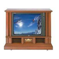
Related product manuals