DISASSEMBLY PROCEDURES
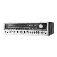
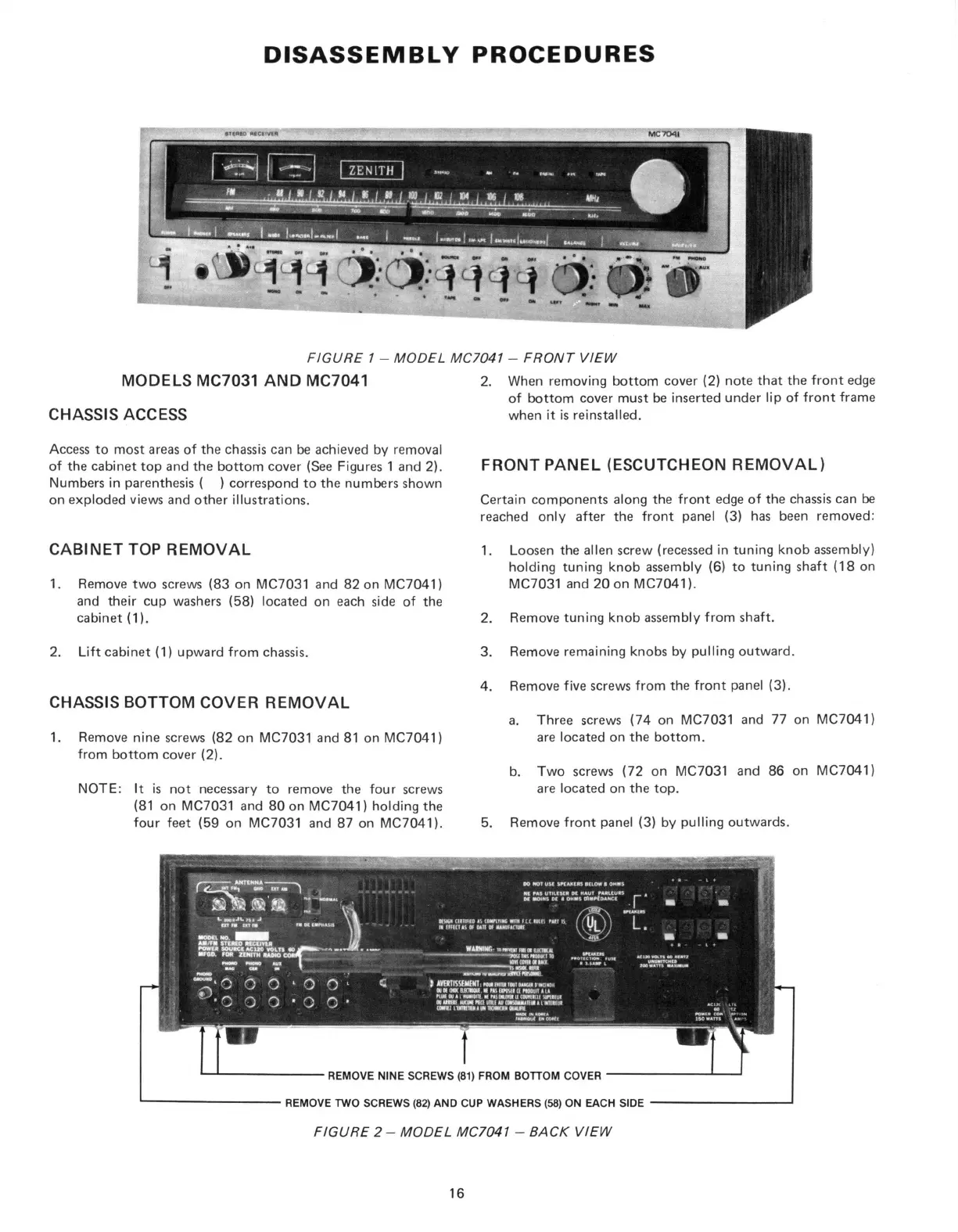
FIGURE 1 - MODEL MC7041 - FRONT VIEW
CHASSIS ACCESS
Access to most areas of the chassis can be achieved by removal
of the cabinet top and the bottom cover (See Figures 1 and 2).
Numbers in parenthesis ( ) correspond to the numbers shown
on exploded views and other illustrations.
CABINET TOP REMOVAL
1.
Remove two screws (83 on MC7031 and 82 on MC7041)
and their cup washers (58) located on each side of the
cabinet (1).
2.
Lift cabinet (1) upward from chassis.
CHASSIS BOTTOM COVER REMOVAL
1.
Remove nine screws (82 on MC7031 and 81 on MC7041)
from bottom cover (2).
NOTE:
It is not necessary to remove the four screws
(81 on MC7031 and 80 on MC7041) holding the
four feet (59 on MC7031 and 87 on MC7041).
2.
When removing bottom cover (2) note that the front edge
of bottom cover must be inserted under lip of front frame
when it is reinstalled.
FRONT PANEL (ESCUTCHEON REMOVAL)
Certain components along the front edge of the chassis can be
reached only after the front panel (3) has been removed:
1.
Loosen the alien screw (recessed in tuning knob assembly)
holding tuning knob assembly (6) to tuning shaft (18 on
MC7031 and 20 on MC7041).
2.
Remove tuning knob assembly from shaft.
3. Remove remaining knobs by pulling outward.
4. Remove five screws from the front panel (3).
a. Three screws (74 on MC7031 and 77 on MC7041)
are located on the bottom.
b. Two screws (72 on MC7031 and 86 on MC7041)
are located on the top.
5. Remove front panel (3) by pulling outwards.
FIGURE 2 - MODEL MC7041 - BACK VIEW
16
 Loading...