To the Service Technician
PRODUCT
SAFETY
SERVICING GUIDELINES
FOR ALL
AUDIO AMPLIFIERS
AND
RADIO RECEIVERS
CAUTION:
No
modification
of any
circuit should
be
attempted.
Service work should
be
performed only
after
you
are
thoroughly
familiar
with
all
of
the
following safety checks
and
servicing guide-
lines.
To
do
otherwise increases
the
risk
of
potential
hazards
and
injury
to the
user.
SAFETY CHECKS
SUBJECT: Fire
&
Shock Hazard
1.
Be
sure that
all
components
are
positioned
in
such
a way
to avoid possibility
of
adjacent components shorts. This
is especially important
on
those chassis which
are
trans-
ported
to and
from
the
repair shop.
2 Always replace
all
protective devices such
as
insulators
and barriers after working
on a
receiver.
3. Check
for
frayed insulation
on
wires including
the AC
cord.
Also check across-the-line components
for
damage
and replace
if
necessary.
4
All
fuses
and
certain resistors
and
capacitors which
are
of
the
flameproof type (shaded
on the
schematic
di-
agrams
and
parts lists) must
be
replaced with exact
Zenith types
to
prevent potential fire hazard.
5 After re-assembly
of the set
always perform
an AC
leak-
age test
on the
exposed metallic parts
of the
cabinet
such
as the
knobs, antenna terminals,
etc. to be
sure
the
set
is
safe
to
operate without danger
of
electrical shock.
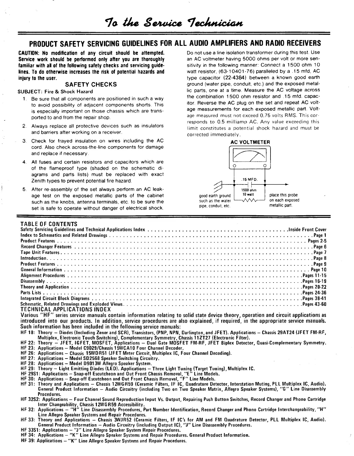
Do
not use a
line isolation transformer during this test.
Use
an
AC
voltmeter having 5000 ohms
per
volt
or
more
sen-
sitivity
in the
following manner: Connect
a 1500 ohm 10
watt resistor, (63-10401-76) paralleled
by a .15 mfd, AC
type capacitor (22-4384) between
a
known good earth
ground (water pipe, conduit,
etc.) and the
exposed metal-
lic parts,
one at a
time. Measure
the AC
voltage across
the combination
1500 ohm
resistor
and .15 mfd.
capac-
itor. Reverse
the AC
plug
on the set and
repeat
AC
volt-
age measurements
for
each exposed metallic part. Volt-
age measured must
not
exceed
0.75
volts
RMS.
This cor-
responds
to 0.5
milliamp
AC. Any
value exceeding this
limit constitutes
a
potential shock hazard
and
must
be
corrected immediately.
good earth ground
such
as the
water
pipe,
conduit,
etc.
place this probe
on each exposed
metallic part.
TABLE
OF
CONTENTS
Safety Servicing Guidelines and Technical Applications Index Inside Front Cover
Index
to
Schematics and Related Drawings Page
1
Product Features Pages
2-5
Record Changer Features Page
6
Tape Unit Features Page
7
Introduction Page
8
Product Features Page
9
General Information Page
10
Alignment Procedures Pages
11-15
Disassembly Pages
16-19
Theory
and
Application Pages 20-22
Parts Lists Pages 24-36
Integrated Circuit Block Diagrams Pages
38-41
Schematic, Related Drawings and Exploded Views Pages 43-60
TECHNICAL APPLICATIONS INDEX
Various
"HF"
series service manuals contain information relating
to
solid state device theory, operation
and
circuit applications
as
introduced into
our
products.
In
addition, service procedures
are
also explained,
if
required,
in the
appropriate service manuals.
Such information has been included
in the
following service manuals:
HF
18:
Theory
-
Diodes (Including Zener and SCR), Transistors, (PNP, NPN, Darlington, and JFET). Applications
-
Chassis 29AT24 (JFET FM-RF,
Multiplex, Electronic Touch Switching), Complementary Symmetry, Chassis 11ZT27 (Electronic Filter).
HF
22:
Theory
-
JFET, IGFET, MOSFET, Applications
-
Dual Gate MOSFET FM-RF, JFET Biplex Detector, Quasi-Complementary Symmetry.
HF
23:
Applications
-
Model C9029/Chassis 15WCA10 Four Channel Decoder.
HF
26:
Applications
-
Chassis 15WDR51 (JFET Meter Circuit, Multiplex
IC,
Four Channel Decoding).
HF
27:
Applications
-
Model SD2568 Speaker Switching Circuitry.
HF
28:
Applications
-
Model D9013W Allegro Speaker System.
HF
29:
Theory — Light Emitting Diodes (LED). Applications
-
Three Light Tuning (Target Tuning), Multiplex
IC.
HF 29S1: Applications — Snap-off Escutcheon
and Out
Front Chassis Removal,
"E"
Line Models.
HF
30:
Applications
—
Snap-off Escutcheon
and Out
Front Chassis Removal,
"F"
Line Models.
HF 31: Theory
and
Applications
-
Chassis 12WGR59 (Ceramic Filters,
IF IC,
Quadrature Detector, Interstation Muting,
PLL
Multiplex
IC,
Audio).
General Product Information
—
Audio Circuitry (including
Two on Two
Speaker Matrix, Allegro Speaker Systems),
"G"
Line Disassembly
Procedures.
HF 32S2: Applications
-
Four Channel Sound Reproduction Input
Vs.
Output, Repairing Push Button Switches, Record Changer
and
Phono Cartridge
Inter Changeability, Chassis 12WGR59 Accessibility.
HF
32:
Applications
- "H"
Line Disassembly Procedures, Part Number Identification, Record Changer
and
Phono Cartridge Inter
Changeability,
"H"
Line Allegro Speaker Systems and Repair Procedures.
HF33:
Theory
and
Applications
-
Chassis 3WJR52 (Ceramic Filters,
IF IC's for AM and FM
Quadrature Detector,
PLL
Multiplex
IC,
Audio).
General Product Information — Audio Circuitry (including Output
IC),
"J" Line Disassembly Procedures.
HF 33S1: Applications — "J" Line Allegro Speaker System Repair Procedures.
HF
34:
Applications —
"K"
Line Allegro Speaker Systems
and
Repair Procedures. General Product Information.
HF
39:
Applications
- "K"
Line Allegro Speaker Systems
and
Repair Procedures.
AC VOLTMETER
 Loading...