THEORY AND APPLICATION
MODELS
MC7031, MC7041,
AND MC7051
Basic circuitry for these models has been covered in Service
Manual HF-38 (Part No. 923-943), however there are certain
points which are also being included, or expanded in this
manual.
MODEL MC7051
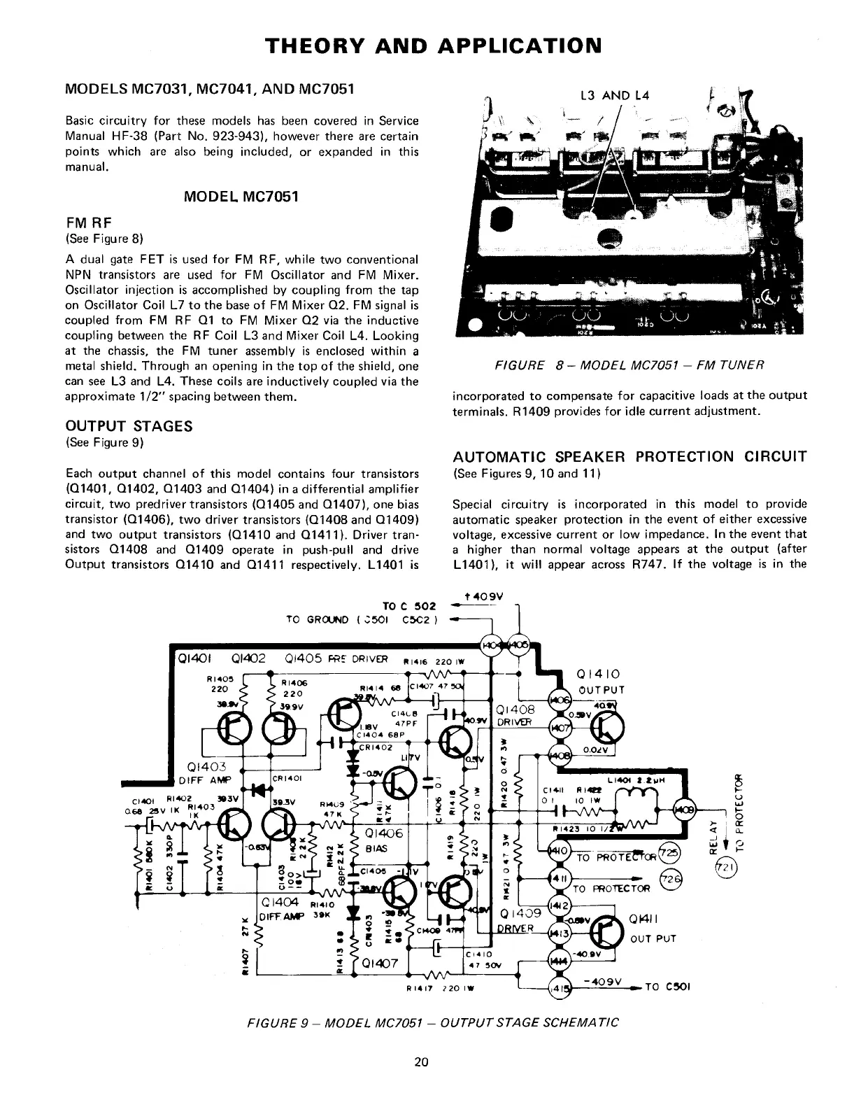
FM RF
(See Figure 8)
A dual gate FET is used for FM RF, while two conventional
NPN transistors are used for FM Oscillator and FM Mixer.
Oscillator injection is accomplished by coupling from the tap
on Oscillator Coil L7 to the base of FM Mixer Q2. FM signal is
coupled from FM RF Q1 to FM Mixer Q2 via the inductive
coupling between the RF Coil L3 and Mixer Coil L4. Looking
at the chassis, the FM tuner assembly is enclosed within a
metal shield. Through an opening in the top of the shield, one
can see L3 and L4. These coils are inductively coupled via the
approximate 1/2" spacing between them.
OUTPUT STAGES
(See Figure 9)
Each output channel of this model contains four transistors
(Q1401,
Q1402, Q1403 and Q1404) in a differential amplifier
circuit, two predriver transistors (Q1405 and Q1407), one bias
transistor (Q1406), two driver transistors (Q1408 and Q1409)
and two output transistors (Q1410 and Q1411). Driver
tran-
sistors Q1408 and Q1409 operate in push-pull and drive
Output transistors Q1410 and Q1411 respectively. L1401 is
FIGURE 8 - MODEL MC7051 - FM TUNER
incorporated to compensate for capacitive loads at the output
terminals. R1409 provides for idle current adjustment.
AUTOMATIC SPEAKER PROTECTION CIRCUIT
(See Figures 9, 10 and 11)
Special circuitry is incorporated in this model to provide
automatic speaker protection in the event of either excessive
voltage, excessive current or low impedance. In the event that
a higher than normal voltage appears at the output (after
L1401),
it will appear across R747. If the voltage is in the
FIGURE 9 - MODEL MC7051 - OUTPUT STAGE SCHEMATIC
20
 Loading...