This document is a user manual for the ZQ280/ZQ280A Vector Variable Frequency Drive Solar Inverter, manufactured by Anhui Zest Electric Co., Ltd. It provides essential information for the safe and effective operation of the device.
The manual emphasizes the importance of safety when working with the VFD. High voltages and currents, including DC, are present, carrying a high level of stored electrical energy in the DC bus capacitors even after power-off, which can be lethal. Only authorized and qualified personnel should work on the VFD.
Machine/system design, installation, commissioning, startup, and maintenance must be performed by trained and experienced personnel who have read the safety information and the manual. Incorrect installation can lead to safety hazards. The VFD is not intended for safety-related applications. The electronic "STOP & START" control circuits should not be relied upon for personnel safety, as they do not isolate mains power voltages from the VFD output. Mains power supply must be disconnected by an electrical safety isolation device before accessing internal parts.
Safety risk assessments of the machine or process system using the VFD are the user's or system integrator's responsibility. The assessment should consider the consequences of VFD failure or tripping during normal operation to ensure a safe stop position without damaging equipment or harming operators. The system integrator must ensure the complete system is safe and designed according to relevant safety standards.
For electrical installation, extreme care is required. Electrical shock risk is always present within the VFD, including the output cable to the motor terminals. If dynamic brake resistors are fitted externally, live contact with the brake resistors and terminals, which are at high DC voltage (typically 300 VDC to 800 VDC), can be lethal. Cables from the VFD to dynamic brake resistors should be double insulated. A mains power supply isolation switch must be fitted to the VFD. The AC supply must be isolated for at least 10 minutes before any work to allow stored charge in the DC bus capacitors to dissipate through internal bleed resistors. It is good practice to check the DC bus voltage with a VDC meter before accessing the VFD bridge. If the VFD input is connected via a plug and socket, be aware that plug pins may be exposed and internally connected to the DC bus capacitors (via the internal bridge rectifier in reversed bias); wait 10 minutes after disconnection for charge dissipation.
Function Description
The ZQ280/ZQ280A is a Vector Variable Frequency Drive (VFD) and Solar Inverter. It controls the speed and torque of AC motors by varying the frequency and voltage of the power supplied to the motor. The device supports both single-phase and three-phase power supplies, with different voltage ranges (220-240VAC and 380-440VAC). It is designed for various motor power ratings, from 0.4KW to 7.5KW.
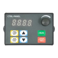
Operating Panel
The device features a control panel with a digital tube display (8.8.8.8) to show frequency, parameters, etc.
- Parameter setting key (PRG SET): Used to read and modify parameter groups or display parameter values.
- Jog and return keys (JOG ESC): Used for VFD jog operation or returning from parameter settings.
- Increment/Decrement keys: Used to increase/reduce parameter numbers or set values.
- RUN button: Starts the VFD in operating panel control mode (inactive in terminal or communication control mode).
- STOP/RES button: Stops the VFD when running; performs a reset when in FAULT status.
- Speed control knob: Adjusts frequency.
After setting parameters, the panel can return to the original interface by powering off/on, selecting parameter d-00 and pressing SET, or long-pressing the SET button.
Basic Operation
The panel displays output frequency (e.g., 50.0) after power-on. Users can navigate through parameters like d-00, d-04 (output current), F0.00, F0.10, and F8.03 using the SET button and increment/decrement keys. The panel automatically returns to the main display after 30 seconds of inactivity.
VFD Running Command Mode Setting
The VFD operation command mode is set by parameter F0.04, offering two types:
- Panel control start and stop (F0.04=0): Press the green button to start, red button to stop. Default is forward rotation; forward/reverse rotation can be set via input terminals X1-X5 (reverse setting is 4).
- Terminal start/stop (F0.04=1): Control via external terminals.
VFD Frequency Setting Method Selection
The frequency setting mode is configured by parameter F0.05:
- F0.05=4: Running frequency set by potentiometer.
- F0.05=2: Running frequency input by AVI (0-10V, can be connected to a potentiometer).
- F0.05=3: Running frequency input by ACI (4-20mA).
- F0.05=1: Controlled by external terminal (digital value increases/decreases frequency).
Installation and Wiring
The manual provides a wiring diagram and terminal function instructions:
- R, S, T terminals: VFD input. For three-phase 220V/380V models, connect to R, S, T. For single-phase 220V models, connect to R, T. An air switch should be used as an over-current protection device. If there is LCDI, choose one with sensitivity above 200mA and reaction period >100ms.
- U, V, W terminals: VFD output, connected to the electrical machine. Connection wire length should not exceed 50 meters to reduce current leakage.
- P+, PB terminals: Connected with braking resistor. Choose an appropriate resistor from the provided list.
- PE terminal: Connected to ground. The VFD must be well-grounded.
- COM: Signal public terminal (zero potential of digital signal).
- X1, X2, X3, X4/485+, X5/485-: Digital inputs. X1 defaults to FWD (F5.02), X2 to REV (F5.03), X3 to multistage speed selection 1 (F5.04). X4/485+ and X5/485- are digital inputs for ZQ280 and RS485+ / RS485- for ZQ280A, defaulting to multistage speed selection 2 (F5.05) and external RST (F5.06) respectively.
- GND: Signal public terminal (zero potential of analog input signal).
- AVI: 0-10V signal input (input resistance >50KΩ).
- 10V: Frequency setting potentiometer power source (+10V, max 10mA).
- ACI: 4-20mA analog input (input resistance 100Ω).
- AO: Analog output (set by F6.10).
- TA, TB, TC: Relay output (contact rating: AC 250V/3A, DC 24V/2A, set by F5.07).
Important Technical Specifications (Selected Parameters)
The manual details numerous function parameters across several groups (F0-FC, d-group). Here are some key ones:
F0 group - Basic running Parameters
- F0.00 (VF Power): Current power of the VFD (0.00-99.99KW).
- F0.01 (Control Mode): 0: V/F Control, 1: SVC mode.
- F0.02 (Running order channel selection): 0: Keyboard command channel, 1: Terminal command channel.
- F0.03 (Frequency given source channel A): Various options including digital setting, AVI/ACI analog setting, keyboard potentiometer, multi-speed, PLC, PID, and communication (ZQ280A Only).
- F0.04 (Frequency given source channel B): Similar options to F0.03.
- F0.05 (Channel A and Channel B calculate result selection): A+B, A-B, MAX(A,B), MIN(A,B).
- F0.06 (Frequency given source selection): Main frequency A, Channel A and B calculate result, Switch Channel A to B, etc.
- F0.07 (digital frequency setting): Initial value of frequency digital given (0-MAX Frequency).
- F0.08 (Max frequency output): Highest output frequency (Upper limit frequency - 400.00Hz, default 50.00Hz).
- F0.09 (Upper limit frequency): Operating frequency cannot exceed this (Lower limit frequency - Max frequency, default 50.00Hz).
- F0.10 (Lower limit frequency): Operating frequency cannot be lower than this (0-Upper limit frequency, default 0.00Hz).
- F0.12 (Acceleration Time 1): Time to accelerate to max output frequency (0-999.9S, default 10.0s).
- F0.13 (Deceleration Time 1): Time to decelerate to zero frequency (0-999.9S, default 10.0s).
- F0.14 (Running direction selection): Forward, Reverse, Forbidden reverse operation.
- F0.17 (Parameter initialization): Restore factory default, clear malfunction records.
F1 group - V/F Control Parameters
- F1.00 (V/F curve set): Beeline, VF square curve, 1.5/1.2 respectively VF power curve, Custom VF curve.
- F1.01 (Torque boost): Improve low frequency torque by voltage compensation (0.0-30.0%, default 3.0%).
- F1.02 (Torque boost cut-off frequency): Frequency above which torque improving function stops (0.0-50.00Hz, default 15.00Hz).
- F1.03 (PWM Carrier frequency): Improves noise and vibration, but increases switch loss and heat (2.0-12.0KHz, model setting).
- F1.10 (AVR function): 0: Forbid, 1: All Effective, 2: Forbid only deceleration.
- F1.11 (Brake ratio): Braking resistor braking ratio (0-100%, default 90%).
F2 group - Vector Control Parameters
- F2.00-F2.03 (ASR Low/High speed Kp/Ki): Proportional and integral gains for speed regulation.
- F2.04 (ASR Low speed switch frequency): (Lower limit frequency - Max frequency, default 10.00Hz).
- F2.05 (ASR High speed switch frequency): (Lower limit frequency - Max frequency, default 30.00Hz).
- F2.06 (Electric slip compensation gain): (0.0-100.0%, default 0).
- F2.10-F2.11 (Current loop Kp/Ki): Proportional and integral gains for current loop.
- F2.14 (SVC motor slip compensation): (0-200%, default 100%).
- F2.19 (Speed control (drive) torque upper limit digital setting): (0.0-200.0%, default 150.0%).
F3 group - Auxiliary Operation Parameters
- F3.00 (Start-up mode): Start frequency, DC brake + start frequency.
- F3.01 (Start frequency): Initial frequency of VFD start (0.50-20.00Hz, default 0.50Hz).
- F3.02 (Holding time of start frequency): Start frequency run time (0.0-60.0s, default 0).
- F3.03 (Start DC brking current): Current for applying DC braking (0.0-100%, default 0.00%).
- F3.04 (Start DC brking time): Duration of applying DC braking (0.0-100.0s, default 0.1s).
- F3.05 (Stop mode): Decelerate stop, Decelerate stop + DC braking, Free stop.
F4 group - Auxiliary Operation 2 Parameters
- F4.00 (Jog forward running frequency setting): (0.00-50.00Hz, default 10.00Hz).
- F4.01 (Jog reverse running frequency setting): (0.00-50.00Hz, default 10.00Hz).
- F4.02 (Jog Accel time): Set jog acceleration time (0.1-999.9s, model setting).
- F4.03 (Jog Decel time): Set jog deceleration time (0.1-999.9s, model setting).
- F4.06 (Jog priority): When VFD is running, jog priority is highest.
- F4.07 (Jump frequency): Avoid mechanical resonance point (0.0-upper limited, default 0.00Hz).
- F4.08 (Jump frequency width): (0.0-10.0Hz, default 0.00Hz).
- F5.00 (FWD/REV mode): Two-line control mode1/2, Three-line control mode1/2.
- F5.01 (Terminal run detection selection at power on): Invalid/valid when electrified.
- F5.02-F5.06 (Input X1-X5 Function): Assigns various functions to digital input terminals, such as forward/reverse control, jog control, external stop, frequency increase/decrease, multi-speed selection, DC braking, RS485 communication (for ZQ280A).
- F5.07 (Programmable relay R output): Configures relay output for various VFD states (e.g., ready to run, running indication, fault, frequency arrival).
- F5.08 (R output delay time): Delay for relay output change (0-999.9s, default 0.0s).
- F5.10 (Frequency arrival detectionrange (FAR)): Output frequency detection width (0.00-15.00Hz, default 5.00Hz).
- F5.13 (UF/DOWN terminal modification rate): Frequency modification rate when UP/DOWN terminal sets frequency (0.10-200.00Hz/s, default 1.00Hz).
- F5.15 (Effective logic setting of input terminal (X1 - X5)): Positive or negative logic for input terminals.
- F5.16-F5.20 (X1-X5 filter coefficient): Adjusts sensitivity of input terminals to interference (0-9999, default 5).
- F6.00-F6.01 (Lower/Upper limit voltage of AVI input): Set AVI limits (0.00-100.0%, default 0.0%/100.0%).
- F6.02-F6.03 (Setting corresponding to AVI lower/upper limit): Corresponds to percentage of upper limit frequency (F0.09).
- F6.04-F6.05 (Lower/Upper limit current of ACI input): Set ACI limits (0.00-100.0%, default 0.0%/100.0%).
- F6.06-F6.07 (Setting corresponding to ACI lower/upper limit): Corresponds to percentage of upper limit frequency (F0.09).
- F6.08 (Constant for filtering time of analog input signal): Filters input signals from AVI, ACI, and panel potentiometer (0.1-5.0s, default 0.1s).
- F6.09 (Error limit of analog input): Restrains frequency fluctuation caused by analog input signal fluctuation (0.0-100.0%, default 0.0).
- F6.10 (A01 output selection): Output frequency, given frequency, output current, output voltage, AVI, ACI.
- F6.11-F6.14 (AO function lower/upper limit, AO output lower/upper limit): Set limits for analog output.
F7 group - PLC, Multi-speed Parameters
- F7.00-F7.06 (Multi-speed frequency 1-7): Set frequencies for multi-speed operation.
- F7.07 (PLC run mode selections): Stop after single cycle, Continuous cycles, Keep final value after single cycle.
- F7.08 (Stop save mode): No save, Save.
- F7.09 (Power down save mode): No save, Save.
- F7.10-F7.16 (1st-7th step running time T1-T7): Set running times for multi-speed steps.
- F7.17-F7.23 (T1-T7 run mode selections): Forward/Reverse, Select acceleration time 1/2.
F8 group - PID Control, MPPT And PV Pump Parameters
- F8.00 (PID feedback trait selection): Positive/Negative trait.
- F8.01 (PID give signal source): Keyboard number, Keyboard Potentiometer, AVI, ACI.
- F8.02 (PID feedback signal source): AVI, ACI.
- F8.03 (Keyboard number PID given): Given value when PID source is keyboard number setting.
- F8.04 (PID instruction acceleration and deceleration time): (0.0-100.0s, default 0.0).
- F8.05 (PID control deviation limit): (0.0-100.0%, default 0.0).
- F8.09 (Proportion gain): (0.00-600.00, default 25.00).
- F8.10 (Integral time): (0.0-100.0s, default 1.0).
- F8.11 (Differential coefficient): (0.00-10.00s, default 0.00).
- F8.12-F8.13 (PID output upper/lower limit): (0.0-100.0%, default 100.0%/0.0%).
- F8.15 (Feedback fault action selection): Run at upper/lower limit frequency, Run according to digital set frequency, Decelerate to stop, Free stop.
- F8.16 (PID feedback loss detection value): (0.0-100.0%, default 0.0).
- F8.17 (PID feedback loss detection time): (0.0-100.0s, default 1.0).
- F8.20 (PID sleep control): No sleep function, Internal wake-up, External input terminal control.
- F8.21 (Sleep frequency): (0.00Hz-Max frequency, default 0.00).
- F8.22 (Sleep delay): (0.0-6000.0s, default 0.0).
- F8.23 (Wake-up deviation): (0.0-100.0%, default 0.0).
- F8.24 (Wake-up delay): (0.0-60.0s, default 0.5).
- F8.27 (Decimal point display settings): 0-3 decimal points.
- F8.36 (MPPT and PV pump function selection): Not enabled, MPPT enabled, PV pump enabled, Both enabled.
- F8.37 (MPPT low point operating Voltage): (0-F8.38V, model setting).
- F8.38 (MPPT high point operating Voltage): (F8.37-1000/500V, model setting).
- F8.39 (PV pump lack of water detect Current Ratio): (0.0-300.0%, default 0.0).
- F8.40 (PV pump Low limit frequemcy): (0.00-99.99Hz, default 0.00).
- F8.41 (PV pump lack of water detect time): (0.0-250.0s, default 0.0).
F9 group - Motor Parameters
- F9.00 (Motor rated power): Model setting.
- F9.01 (Motor rated voltage): (1-500V, model setting).
- F9.02 (Motor rated current): (0.01-99.99A, model setting).
- F9.03 (Motor rated speed): (0-60000Krpm, model setting).
- F9.04 (Motor rated frequency): (1-400.00hz, default 50.00Hz).
- F9.05 (Parameters self-adjustment selections): No operation, Static self-tuning.
- F9.06-F9.11 (Motor stator/rotor resistance, inductance, mutual inductance, no-load current): Model setting.
FA group - Protect Parameters
- FA.00 (Motor overload protection): Invalid, Valid.
- FA.01 (Motor overload protection curve coefficient): (30%-110%, default 100%).
- FA.02 (Undervoltage protection level): (150-280V, 300-480V, default 180/360V).
- FA.03 (Overvoltage Stall Enable): Disabled, Enabled.
- FA.04 (Over-voltage limit level): (350-380V, 660-760V, default 375/660V).
- FA.05 (Current limit level): (30-200%, default 150%).
- FA.06 (Frequency drop rate at current limit): (0-99.99Hz/s, default 0).
- FA.07 (Current limiting action selection): Invalid, Acceleration/deceleration valid, Constant speed invalid, Valid for all.
- FA.08 (Overload pre-alarm level): (120-150%, default 120%).
- FA.09 (Overload pre-alarm delay): (0.0-15.0s, default 5.0s).
- FA.10 (Oscillation suppression coefficient): (0-200, default 30).
- FA.11 (Amplitude suppression coefficient): (0-1000, default 20).
- FA.12 (Oscillation suppression lower limit frequency): (0.0-FA.13, default 5.00Hz).
- FA.13 (Oscillation suppression upper limit frequency): (FA.12-200.00Hz, default 50.00Hz).
- FA.14 (Cycle-by-cycle current limit selection): Selects current limit for acceleration, deceleration, constant speed.
- FA.15 (Cycle-by-cycle current limit level): VFD rated current (80-200%, default 180).
- FA.16 (Malfunction auto-reset times): (0-10, default 0).
- FA.17 (Malfunction auto-reset interval): (0.5-25.0s, default 3.0S).
- FA.18 (VF overcurrent, overvoltage suppression selection): Not enabled, Overcurrent suppression enable, Overvoltage Suppression enable, Both enabled.
- FA.19 (VF overcurrent suppression Kp): (0-100, default 20).
- FA.20 (VF Double-speed overcurrent stall action current compensation coefficient): (50-200, default 50).
- FA.21 (VF overvoltage suppression Kp): (0-100, default 60).
- FA.22 (VF Overvoltage Stall Rise Maximum Frequency): (0-50, default 5).
- FA.23 (VF Overvoltage Stall Regulator Kp): (0-100, default 80).
- FA.24 (Power-off and under-voltage shutdown mode): Report undervoltage fault, free stop; No undervoltage fault reported, stop according to set stop mode (F3.05).
FB group - Display And Special Parameters
- FB.00 (Running monitoring parameters): Default display item of main monitoring interface (0-15, default 0).
- FB.01 (Stop monitoring parameters): (0-15, default 1).
- FB.02 (Motor speed display coefficient): Corrects display error of speed scale (0.01-99.99, default 1.00).
- FB.03-FB.09 (Current Malfunction, Last malfunction, First two malfunction, Malfunction Bus Voltage, Malfunction out Current, Malfunction given frequency, Malfunction running frequency): Fault records and monitoring.
- FB.10 (Counting and Timing Modes): Configures count arrival processing and timed arrival processing.
- FB.11-FB.13 (Counter reset value setting, Counter detection value setting, Timing time setting): (0-9999, 0-9999s).
FC group - Communication Control Function Parameter
- FC.00 (Communication baud rate): (0:1200 to 5:38400, default 3:9600).
- FC.01 (Modbus data format): Various parity and data bit settings (default 6: no parity, <8,N,2>).
- FC.02 (485 communication address): (1-247, default 1).
- FC.03 (Modbus communication overtime fault time): (0.0-600.0s, default 10.0s).
- FC.05 (Modbus communication fault act mode selections): No checkout overtime fault, Alarm, Forced stop.
dGroup - Monitoring parameter group and fault record
- d-00 (Output frequency): (0.00-400.00Hz, 0.01Hz unit).
- d-01 (Settings frequency): (0.00-400.00Hz, 0.01Hz unit).
- d-02 (Output voltage): (0-999V, 1V unit).
- d-03 (Bus volage(V)): (0-999V, 1V unit).
- d-04 (Output current): (0.0-999.9A, 0.1A unit).
- d-05 (Motor rotation speed(RPM/min)): (0-60000 RPM/min, 1 unit).
- d-06 (Analog input AVI(V)): (0.00-10.00V, 0.01 unit).
- d-07 (Analog input ACI(mA)): (0.00-20.00mA, 0.01 unit).
- d-08 (Analog output AO1(V)): (0.00-10.00V, 0.01V unit).
- d-09 (Input and output terminal status): (0-3FH, 1H unit).
- d-10 (Radiator temperature1): (0.0°C-+999.9°C, 0.1°C unit).
- d-11 (PID setting value): (PID range lower limit - PID range upper limit, 0.01V unit).
- d-12 (PID feedback value): (PID range lower limit - PID range upper limit, 0.01V unit).
- d-13 (Current count): (0-9999, 1 unit).
- d-14 (Current timing value(S)): (0-9999s, 1s unit).
- d-15 (Accumulated running time of the machine(h)): (0-9999h, 1h unit).
- d-16 (Accumulated electrify time of the machine(h)): (0-9999h, 1h unit).
Fault Codes and Troubleshooting
The manual lists various fault codes (e.g., OU1(1) Over voltage in Acc process, OCC1(4) Hardware Over-current in Acc process, LU(13) Undervoltage, OH(14) Overheat, ELT Water shortage malfunction) with possible reasons and troubleshooting steps. For example, for "Over voltage in Acc process," possible reasons include abnormal supply voltage or restarting with a rotating motor, and troubleshooting involves checking the power supply or starting after setting as DC braking. For "Overheat," reasons include high ambient temperature, small space, blocked air duct, or cooling fan not running, with solutions like improving environment, adjusting space, cleaning airways, and checking the fan.
Communication Data Structure (Modbus-RTU)
The VFD supports Modbus-RTU slave communication protocol via RS485. Users can centralize control, set running commands, modify/read parameters, and get status/fault info.
- Parameter data communication address: F0-FP group parameters have high sixteen bits 00-0D, low sixteen bits are serial number (e.g., F0-16 is 0010H).
- Product non-parametric data:
- d monitoring parameters: Address 7000H-70FFH (e.g., d-11 is 700BH).
- Inverter fault description: Address 8000H.
- Inverter running status: Address 3000H (1: Forward operation, 2: Reverse operation, 3: Stop).
- Control commands: Address 2000H (0001: Forward running, 0002: Reverse operation, etc.).
- Communication settings: Address 1000H (data range -10000 to 10000, corresponding to -100.00% to 100.00%).
- Modbus-RTU protocol: Supports reading/writing Word-type parameters (command 0x03 for read, 0x10 for write). Data frame fields include Slave address, Command code, Parameter address H/L, Number of parameters H/L, Data H/L, CRC CHK low/high.
- Parameter address marking rules: High byte 00-0F for F group, 70 for d group. Low byte 00-FF. (e.g., F3-12 is 0x030C).
Maintenance Features
The manual implicitly covers maintenance through its troubleshooting section, which guides users on diagnosing and resolving common issues like overvoltage, overcurrent, undervoltage, and overheating. It also mentions parameter initialization to restore factory defaults or clear malfunction records (F0.17). Regular checks of power supply, load, wiring, and cooling fan are implied for preventing faults. The filter coefficients for digital inputs (F5.16-F5.20) can be adjusted to improve resistance to interference, which is a form of preventive maintenance.