EasyManua.ls Logo

ZF Marine ZF 25 - User Manual

ZF Marine ZF 25
5 pages
Print Icon
To Next Page IconTo Next Page
Loading...
10
Operating Manual ZF/ZFE 25 A - ZF/ZFE 85 IV
ENGLISH
Section
1.1
Introduction
...............................
2.1
Gear Identification
....................
3.1
Description
...............................
4.1
Installation
.................................
11
5.1
Operation
...................................
11
6.1
Maintenance
.............................
12
7.1
Troubleshooting
........................
13
8.1
Technical Data
..........................
14
9.1
Warranty
...................................
14
10.1
List of recommended fluids
......
61
11.1
Dealer List
................................
62
12.1
Installation layout
.....................
63
13.1
Warranty Card
..........................
73
1.1
Introduction
1.1.1
C
USTOMER
S
R
ESPONSIBILIT
Y
The Customer/Operator is responsi
-
ble to perform the necessary safety
checks to ensure that lubrication, cool
-
ing, maintenance and recommended
practices are strictly followed for safe,
enjoyable operation.
All Transmission units are covered by
a guarantee. Therefore: In respect to
the handling of the transmission units
the instructions stated in this manual
are to be strictly followed.
C
AUTION
The manufacturer is not liable for
any damages or losses caused by
faulty installation, wrong handling
of the equipment and/or deficient
maintenance.
The Customer has to make sure,
that any external forces, as well
as vibration caused by torsion and
bending, are avoided.
The interaction between engine,
shaft and propeller may lead to
torsional vibration, producing a
hammering noise of gears and
might damage the engine and/or
transmission.
The Supplier is not liable for such
torsional vibration inherent to the
installation.
This manual includes, among others,
the following three main chapters:
1.1.2
D
ESCRIPTION
This part briefly describes function,
operation and design of the ZF/ZFE
types A/H/IV.
1.1.3
O
PERATION
This part describes the procedures for
Operation and all necessary safety
measures.
1.1.4
M
AINTENANCE
This part contains all maintenance and
service tasks to be performed by the
operator.
Whenever the terms «right, left, star
-
board, port» are used in this manual,
they always refer to the installed
transmission in direction of forward
movement.
Important information related to tech
-
nical reliability and operational safety
are highlighted by the identifying words
as follows:
WARNING
Any procedure, practice, condition,
statement etc., which is not strictly
followed, could result in injury or
death of personnel.
C
AUTION
Any procedure, practice, condition,
statement etc., which is not strictly
followed, could result in damage or
destruction of equipment.
N
OTE
:
Applies to technical require
-
ment to which the user of the equip
-
ment must pay particular attention.
WARNING,
C
AUTION
and
N
OTE
always precede the text to which they
apply.
2.1
Gear Identification
The identification plate is affixed to the
reverser.
An example of an identification plate
is shown in Fig. 1:
A
Transmission ratio propeller rota
-
tion opposite to a engine rotation.
B
Transmission Serial Number.
C
Every year a new progressive letter
is assigned.
D
Transmission part number.
E
Transmission version.
F
Transmission ratio propeller rota
-
tion same as engine rotation.
G
Transmission Type.
Significance of transmission designa
-
tions:
L
Version of transmission
H
Design of transmission
M
Nominal transmission ratio
I
Size of transmission
Position the control lever (refer to the rela
-
tive figures for the various models):
Figure 2: Type
ZFE 25 A-ZFE 45 A
- ZFE 63 A-ZFE 80 A
- ZFE 80 -1 A-ZFE 85 A
Figure 3: Type
ZFE 25 - ZFE 45-1
- ZFE 63.
Figure 4: Type
ZFE 63 IV - ZFE 80 IV
- ZFE 80-1 IV-ZFE 85 IV.
Figure 5: Type
ZFE
(Electronic
version).
Electric valves pos. «A» and «B» corre
-
spond to shifting lever «A» and «B» pos.
- Electric valves
12 V DC, 24 V DC.
- Version
A / H / IV.
3.1
Description
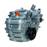
The ZF / ZFE A/H/IV marine trans
-
mission is a hydraulically activated
helical gear unit, developed for use in
commercial and pleasurecraft and de
-
signed as a three shaft type gearbox.
(Four shafts design for IV type).
The transmission is provided with a
disc-type reversing clutch mounted
on the input shaft and supplied with
hydraulic pressure from a fluid pump.
Operation of the fluid pump is depend
-
ent on the engine speed; the pump is
integrated in the control block.
The transmission is lubricated by
splash and force-feed lubrication.
3.1.1
ZFE OPTION
A head, astern, clutch disengagement
are operated electrically by ON/OFF
electric valves.
Electronic control block includes «get
home» features as well.
A simple mechanical device permits
manual engagement of the clutch.
Figure 6:
1
From cooler
2
Neutral safety switch
3
To cooler
4
Connecting thread for temperature
sensor
5
Control block
6
Connection for shifting pressure
control

Questions and Answers

Summary

Introduction

Customers Responsibility

Outlines customer's duty for safe operation, maintenance, and following manual instructions.

Description

Briefly describes function, operation, and design of ZF/ZFE types A/H/IV.

Operation

Describes operational procedures and necessary safety measures.

Maintenance

Covers maintenance and service tasks to be performed by the operator.

Gear Identification

Significance of Transmission Designations

Explains the meaning of transmission designators like type, version, ratio, and size.

Description

ZFE Option

Details electrical operation of clutch engagement and 'get-home' features for ZFE models.

Installation

Operation Procedure

Details procedures for operating the transmission, including shifting and temperature checks.

Operation

Covers pre-shipment testing, normal operation, and emergency shifting procedures.

A and H Versions

Explains shifting positions for A/H versions based on lever or electric valve operation.

IV Versions

Explains shifting positions for IV versions based on lever or electric valve operation.

Moving in Tow or Anchoring

Advises on propeller rotation during towing or anchoring and engine off conditions.

Maintenance

Fluid Level Check

Provides step-by-step instructions for checking the transmission fluid level.

Fluid Change

Details the procedure and schedule for changing transmission fluid and filter.

Remove Fluid Filter

Step-by-step guide to removing the fluid filter element for replacement.

Draining Transmission Fluid

Instructions on how to drain the transmission fluid using a suction pump.

Filling Up with Transmission Fluid

Specifies fluid types and quantities for filling the transmission.

Insert Fluid Filter into Housing

Guide for installing the new fluid filter element into the housing.

Trial Run

Instructions for performing a trial run after an oil change.

Storage

Advises on preparing the transmission for long-term storage to prevent corrosion.

Troubleshooting

High Fluid Temperature

Lists possible causes and remedies for high transmission fluid temperature.

Fluid on Transmission Housing

Identifies causes and solutions for leaks on the transmission housing.

Fluid and Water Mixed

Discusses causes and remedies for fluid contamination with water.

Shifts Hard

Provides potential causes and solutions for hard gear shifts.

Slow Engagement

Outlines reasons and fixes for slow engagement of gears.

No Movement of the Boat

Addresses issues causing the boat to not move, including electric supply faults.

Technical Data

Pleasure Duty

Indicates duty cycle classification for pleasure craft applications.

Continuous Duty

Indicates duty cycle classification for continuous operation.

Warranty

Standard Warranty

Details the standard warranty coverage, limitations, and duration for ZF transmissions.

Torsional Responsibility and Torsional Couplings

Discusses responsibility for torsional compatibility and the importance of torsional limit stops.

ZF Marine ZF 25 Specifications

General IconGeneral
BrandZF Marine
ModelZF 25
CategoryMicrophone system
LanguageEnglish

Related product manuals