9
GB
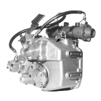
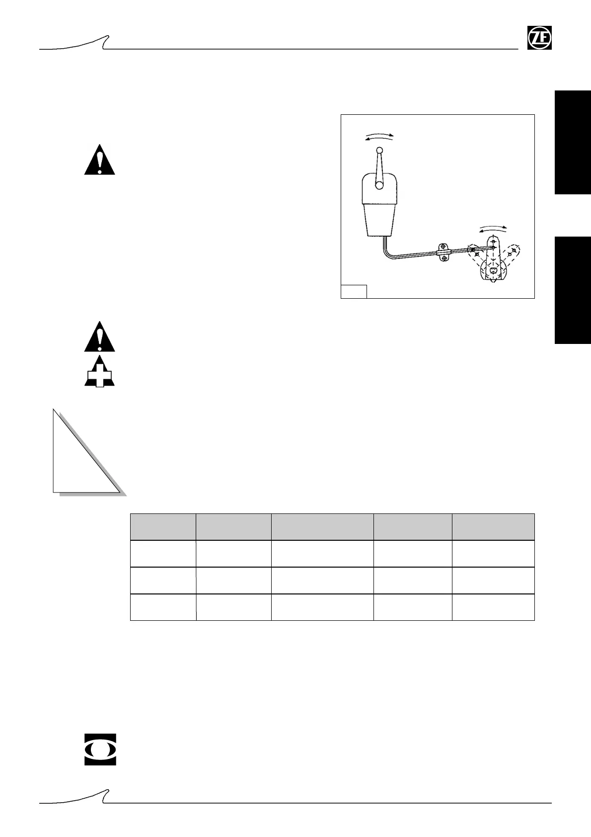
CONTROL VALVE SHIFT CONTROL LINKAGE
When installing the shift control linka-
ge,make sure the travel on the lever takes
it right to the travel limit, when operated
from the bridge console.
If it doesn't, this could result in the burning
of the clutches because the oil flow rate
will be too low.
Fig. 9
2
TECHNICAL DATA
S E C T I O N
ZF 280
ZF 280A
Type
* Oil capacity
(dm
3
)
Pump delivery
(l/min at 1000rpm)
**Op. pressure
(bar)
**Op.
temperature (°C)
4 ÷ 5 8 23 ÷ 24 40 ÷ 80
Notes
* ) gearbox without optionals; (see "oil level check")
**) reference r.p.m: 1500
Use holes [5] and [15], as shown on page 7, for taking the readings.
You are advised to fit a pressure gauge (range 0-50 bar) into hole [15] and an oil temperatu-
re sensor into hole [5].
ZF 280 IV
4 ÷ 5 8 23 ÷ 24 40 ÷ 80
5 ÷ 6 8 23 ÷ 24 40 ÷ 80
TOWING
Towing can be done continuously for 8 hours. Check that the oil temperature does not go
over 80°C.
The position of the control lever is of no importance when the engine is off.
Do not perform any operations on the transmission during towing, as the propeller
may start turning.
 Loading...