10
ZF PADOVA
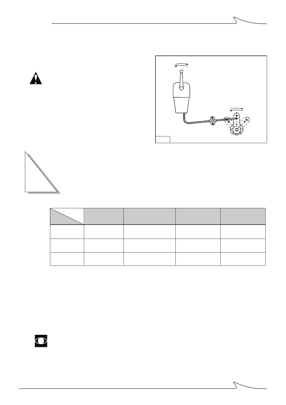
CONTROL VALVE SHIFT CONTROL LINKAGE
When installing the shift control linkage,
make sure the travel on the lever takes it
right to the travel limit, when operated from
the bridge console.
If it doesn't, this could result in the burning of
the clutches because the oil flow rate will be
too low.
Fig. 6
TECHNICAL DATA
2
Notes
* ) gearbox without optionals; (see "oil level check")
**) reference r.p.m: 1500
Use holes [5] and [15], as shown on page 8, for taking the readings.
You are advised to fit a pressure gauge (range 0-50 bar) into hole [15] and an oil
temperature sensor into hole [5].
SECTION
*Oil capacity Pump delivery **Op.pressure Op.
(dm
3
) (l/min at 1000 rpm) (bar) temperature (°C)
ZF 550 16 ÷ 18 22 23 ÷ 24 40 ÷ 80
ZF 550 A 16 ÷ 18 22 23 ÷ 24 40 ÷ 80
ZF 550 V 16 ÷ 18 22 23 ÷ 24 40 ÷ 80
Type
 Loading...