4.5 MEASURING THE BEARING CLEARANCE/ADJUSTING THE PRETENSION
OF BEARINGS
4.5.1 General
The required pretension/play of bearings of the indivi-
dual shafts in the housing is obtained by using shims
of different thickness under the outer races of the taper
roller bearings. Shims which have been removed dur-
ing disassembly may be reused.
First adjustment must refer to bearing clearance.
Take out from the front cover (Fig. 5-1) at least shims of
0.2 mm (0.0079 in.) thickness from the shims packages
which were removed during disassembly.
Adjustment values
Pretension (mm)
Shaft Input Intermediate Output
ZF 80 A - ZF 80-1 A 0.02-0.12 0.00-0.12 0.00-0.12
ZF 85 A - ZF 80 A ] 0.02-0.12 0.00-0.12 0.1-0.15
ZF 63 A - ZF 63 0.02-0.12 0.00-0.12 0.05-0.15
Pretension (inches)
Shaft Input Intermediate Output
ZF 80 A - ZF 80-1 A 0.001-0.005 0.000-0.005 0.000-0.005
ZF 85 A - ZF 80 A ] 0.001-0.005 0.000-0.005 0.004-0.006
ZF 63 A - ZF 63 0.001-0.005 0.000-0.005 0.002-0.006
] (ZF 85 A DERIVATE VERSION)
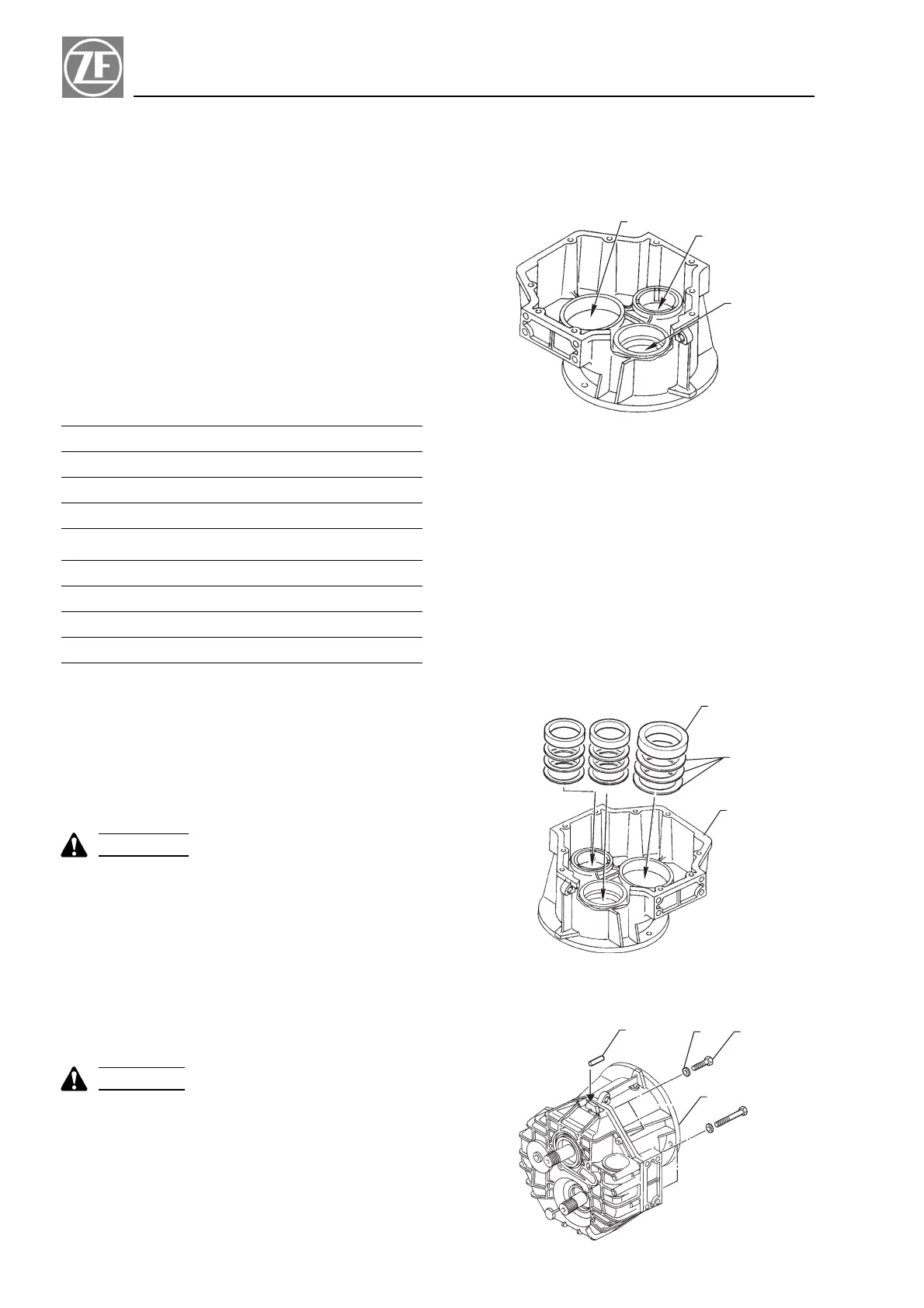
4.5.2 Mounting outer races of tapered roller
bearings into housing
Heat input half housing (item 1, Fig. 5-2) in an oven to
approx. 120 ëC (248 ëF) and insert shims (item 2) and
outer races (item 3) of bearings into it.
|
WARNING
|
Handle heated housing half only with protective
gloves!
When half housing has cooled down to ambient tem-
perature, press outer races carefully down using a cop-
per/brass punch.
4.5.3 Inserting gear set into housing
Finish housing mating face halves with an oilstone.
|
CAUTION
|
Make sure to keep any dirt out of housing.
.
Holding the half housing on a swiveling stand, in-
sert gears into it.
.
Mount input housing half (item 1, Fig. 5-3) with all
bolts, lock washers (item 2 and 3, Fig. 5-3) and par-
allel pins (item 4, Fig. 5-3).
.
Tightening torque of bolts: 40 Nm (30 ft.lb.).
22
Repair Manual and Spare Parts List Section 4
3
2
1
FIG. 5 - 1
1
2
3
FIG. 5 - 2
4
3
2
1
FIG. 5 - 3
 Loading...