4.6 CONTROL BLOCK
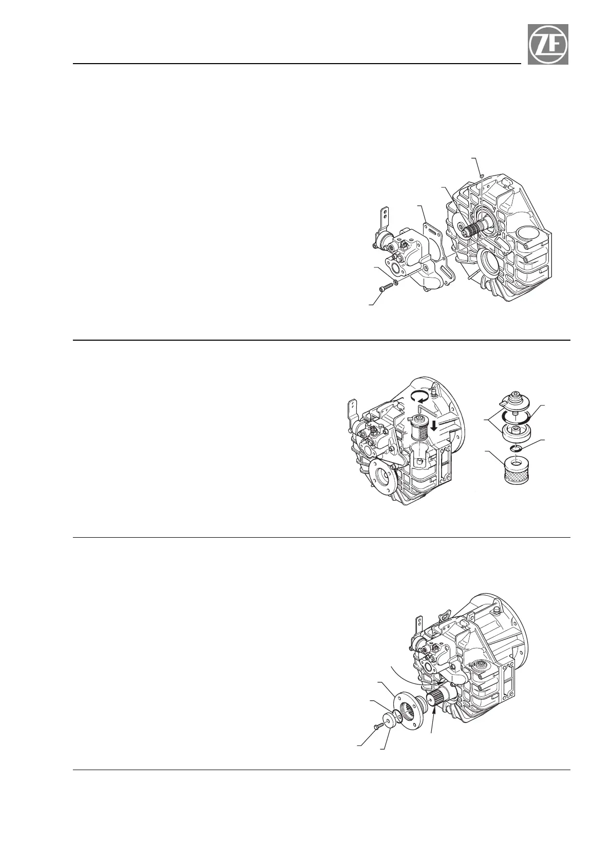
4.6.1 Mounting the control block
NOTE
Piston rings (item 1, Fig. 6-1) have to be replaced, if
thickness is less than 2.39 mm (0.094in).
a) Insert key (item 2, Fig. 6-1) into groove of shaft.
b) Place new seal (item 3, Fig. 6-1) onto control block.
c) Align key and slot in rotor pump.
d) Slide control block carefully on input shaft.
e) Insert lock washers (item 4, Fig. 6-1) on socket head
bolts (item 5, Fig. 6-1) and provide screw threads
each with a drop of Loctite 243.
f) Tight control block bolts. Tightening torque:
18 Nm (14 ft.lb.).
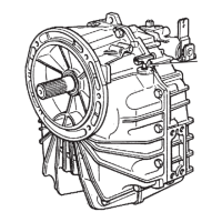
4.7 FLUID FILTER
4.7.1 Mounting the fluid filter
.
Wet O-rings (item 1 and 2, Fig. 7-1) with some ATF
fluid and mount them.
.
Install filter element (item 3, Fig. 7-1) into the trans-
mission.
.
Lock cover (item 4 Fig. 7-1) to the transmission
using an allen wrench. Tightening torque: min. 5
Nm - max 8 Nm (min. 4 ft.lb. - max 6 ft.lb.)
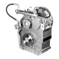
4.8 OUTPUT FLANGE
Provide spline (X) of output shaft with a thin coat of Loc-
tite 245 and sealing lip (Z) of shaft seal with a thin coat
of ATF fluid. (Fig. 8-1)
Fit output flange (item 1, Fig. 8-1).
Provide O-ring (item 2, Fig. 8-1) with ATF fluid and in-
sert into output flange.
Tight output flange down on output shaft with bolt (item
3, Fig 8-1) and washer (4).
Tightening torque:
ZF 63 A - ZF 63 : 100 Nm (74 ft.lb.)
ZF 80 A - ZF 80-1 A : 100 Nm (74 ft.lb.)
ZF 85 A : 100 Nm (74 ft.lb.)
25
Repair Manual and Spare Parts List Section 4
1
2
3
4
5
FIG. 6 - 1
4
2
1
3
FIG. 7 - 1
1
2
4
3
X
Z
FIG. 8 - 1