Do you have a question about the Zibro Kamin SRE 166 (Type B) and is the answer not in the manual?
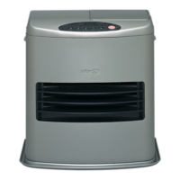
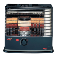
Diagrams illustrating the external components of the SRE 156 and SRE 166 heater models.
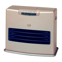
Diagrams illustrating the external components of the SRE 176 heater model.
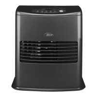
Diagrams illustrating the external components of the SRE 250 and SRE 260 heater models.
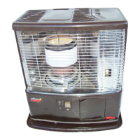
Diagrams illustrating the external components of the Oslo, SRE 701, 702, and 703 heater models.
Detailed diagrams showing internal components of different heater models.
Explanation of the burning process and technical specifications of the heaters.
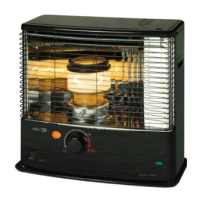
Operational controls and indicators for SRE 156 and SRE 166 models.
Operational controls and indicators for the SRE 176 model.
Operational controls and indicators for SRE 250 and SRE 260 models.
Operational controls and indicators for Oslo, SRE 701, 702, and 703 models.
Step-by-step disassembly for common models: SRE 156, 166, Oslo, 701, 702, 703.
Step-by-step disassembly procedure for the SRE 176 heater.
Step-by-step disassembly procedure for the SRE 250 heater.
Step-by-step disassembly procedure for the SRE 260 heater.
Details on checking and connecting terminals of the main circuit board for various models.
Role, resistance, and replacement guidelines for the heater igniter.
Importance, connection, replacement, and resistance standards for the burner thermistor.
Maintenance and cleaning procedures for the fuel pump, including flow rate determination.
Function, output voltages, and potential issues with the heater's transformer.
Adjustment of the air flow damper for different altitude levels and its importance for combustion.
Procedure for correctly setting the burner ring and burner assembly.
Details on adhering the burner mat and its importance for preventing oscillated combustion.
Information on the overheat protector device and its types.
Procedures for disassembling the blower motor and air intake fan for different models.
Lists the product model names and their corresponding main circuit board model numbers.
Specifies the voltage, frequency, temperature, and humidity conditions for operation.
Details the output currents for the igniter, fuel pump, blower motor, and circulation fan motor.
Provides timing charts detailing operational sequences for various heater models.
Comprehensive technical specifications covering various parameters of the main circuit board.
Details various timing parameters (T1-T10) for different heater models.
Details on detected current, rod leak resistance for primary and secondary flame rods.
Specifies temperature settings, resistance values, and control logic for the room thermistor.
Details resistance values at different temperatures and detection of wire breaks for the burner thermistor.
Explains ventilation calculations, correction values, and safety operation logic.
Describes the function and display patterns of various lamps, error codes, and burning modes.
Explains the functionality of the power button, tact switches, timer buttons, and display indications.
Details on ventilation safe mode, low burning, circulation fan control, and high burning settings.
Explains how to display primary flame status and burning modes using buttons.
Explains how to display burning modes using the UP button.
Describes how to display failure time using the extension button and the calculation formula.
Explains how to recall previous error codes by pressing buttons when the power is off.
Describes how to display ventilation status and values by pressing buttons during operation.
Maintains current burning mode regardless of room temp when specific buttons are pressed.
Details circulation fan motor post-purge conditions after power failure based on burner thermistor resistance.
Conditions for enabling/disabling relay stuck prevention based on burner thermistor resistance.
Maintains time and burning for a fixed period, with conditions for mode changes.
Describes display turn-off and wake-up behavior for stand-by mode.
Forcibly changes burning to Med. burning if High burning runs continuously for over two hours.
Procedure for entering and operating check mode, including display indications and button functions.
Explains differences between normal and check mode operation, and specific behaviors in check mode.
Details the different types of buzzer sounds (A, B, C) and their durations.
Explains the function of storing settings and the expected backup time and life.
Troubleshooting steps for E-0 error related to high limit switch or circulation fan failure.
Troubleshooting for F-0 error related to main circuit board soldering or power restoration.
Troubleshooting for E-1 error related to room thermistor malfunction or disconnection.
Troubleshooting for F-1 error related to igniter, burner thermistor, or main circuit board issues.
Troubleshooting for E-2 error related to flame detection, igniter, transformer, or fuel pump issues.
Troubleshooting for E-5 error related to tip-over switch actuation or malfunction.
Troubleshooting for E-6 error related to incomplete combustion or air flow issues.
Troubleshooting for E-7 error related to high room temperature or room thermistor failure.
Troubleshooting for E-8 error related to blower motor malfunction or Hall IC failure.
Troubleshooting for E-9 error related to secondary flame rod or installation issues.
Describes troubleshooting for flickering bar display and related indicators.
Explains issues like no operation lamp light, odor during operation, and time disorder.
Instructions on how to activate and interpret the flame current display function.
Explanation of Least-Significance-Bit in the context of digital display values.
Formula and example for calculating flame current from digital display values.
| Model | SRE 166 (Type B) |
|---|---|
| Category | Heater |
| Heater Type | Paraffin Heater |
| Fuel Type | Paraffin |
| Safety Features | Overheat protection, tip-over protection |