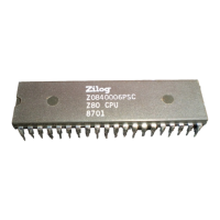
Z80 CPU
User’s Manual
UM008005-0205 List of Figures
xv
List of Figures
Figure 1. Z80 CPU Block Diagram . . . . . . . . . . . . . . . . . . . . . . . . . . . . .2
Figure 2. Z80 CPU Register Configuration . . . . . . . . . . . . . . . . . . . . . . .3
Figure 3. Z80 I/O Pin Configuration . . . . . . . . . . . . . . . . . . . . . . . . . . . .7
Figure 4. Basic CPU Timing Example . . . . . . . . . . . . . . . . . . . . . . . . . .12
Figure 5. Instruction Op Code Fetch . . . . . . . . . . . . . . . . . . . . . . . . . . .13
Figure 6. Memory Read or Write Cycle . . . . . . . . . . . . . . . . . . . . . . . . .14
Figure 7. Input or Output Cycles . . . . . . . . . . . . . . . . . . . . . . . . . . . . . .15
Figure 8. Bus Request/Acknowledge Cycle . . . . . . . . . . . . . . . . . . . . . .16
Figure 9. Interrupt Request/Acknowledge Cycle . . . . . . . . . . . . . . . . . .17
Figure 10. Non-Maskable Interrupt Request Operation . . . . . . . . . . . . .18
Figure 11. HALT Exit . . . . . . . . . . . . . . . . . . . . . . . . . . . . . . . . . . . . . . .19
Figure 12. Power-Down Acknowledge . . . . . . . . . . . . . . . . . . . . . . . . .19
Figure 13. Power-Down Release Cycle No. 1 . . . . . . . . . . . . . . . . . . . .20
Figure 14. Power-Down Release Cycle No. 2 . . . . . . . . . . . . . . . . . . . .20
Figure 15. Power-Down Release Cycle No. 3 . . . . . . . . . . . . . . . . . . . .21
Figure 16. Mode 2 Interrupt Response Mode . . . . . . . . . . . . . . . . . . . . .26
Figure 17. Minimum Z80 Computer System . . . . . . . . . . . . . . . . . . . . .28
Figure 18. ROM and RAM Implementation . . . . . . . . . . . . . . . . . . . . . .29
Figure 19. Adding One Wait State to an M1 Cycle . . . . . . . . . . . . . . . .30
Figure 20. Adding One Wait State to Any Memory Cycle . . . . . . . . . .31
Figure 21. Interfacing Dynamic RAMs . . . . . . . . . . . . . . . . . . . . . . . . .32
Figure 22. Shifting of BCD Digits/Bytes . . . . . . . . . . . . . . . . . . . . . . . .36

 Loading...