Do you have a question about the ZiLOG Z80 and is the answer not in the manual?
Details on the top side of the PCB.
Details on the bottom side of the PCB.
Technical diagram of the Z80 PIO module.
Lists corrections for PCB labelling issues.
Information on obtaining the printed circuit board.
DIP switch for address selection.
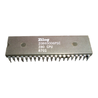
Specifications for the Z80 PIO chip.
Specifications for the main header connector.
Fit and solder IC sockets for U1, U2, and U3.
Fit and solder capacitors C1, C2, C3, and C4.
Fit and solder resistor pack RP1.
Fit and solder connector P1.
Setting up interrupt daisy chain signals IEI and IEO.
Setting the module's I/O address using DIP switch SW1.
| Manufacturer | ZiLOG |
|---|---|
| Introduction Year | 1976 |
| Clock Speed | 2.5 MHz to 20 MHz |
| Data Width | 8-bit |
| Address Width | 16-bit |
| Instruction Set | Z80 |
| Transistor Count | 8, 500 |
| Package | 40-pin DIP |
| Category | Microprocessor |
| Memory Address Space | 64 KB |
| Voltage Supply | 5V |