26
Configuring the PIO Module
Theonly jumpers onthe PIOboard arefor interruptdaisy chainsignalsIEI andIEO. If
yoursystem has more thanone device usinginterrupt mode 2, it willbe necessary
to set upan interrupt daisychain.
Thisis fullydescribedin the Z80peripheralsdata sheet, butessentially itrequires
linkingthe output (IEO)of one interrupt generatingdeviceto the input(IEI) ofthe
next,and so on. Theposition inthe chain determinesthe device’s interrupt priority.
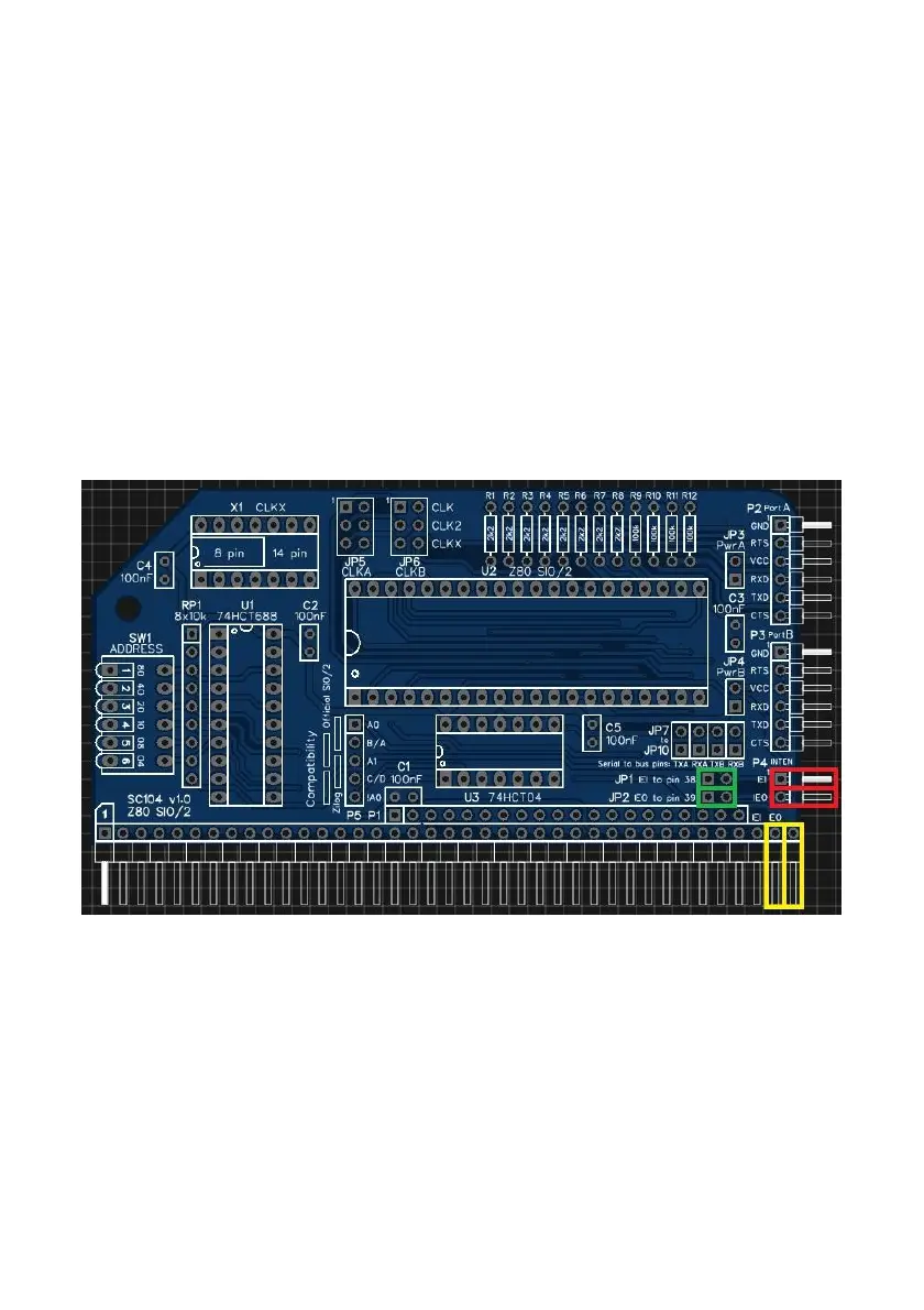
Theillustrationshowsthe connections required whenusingexternal Dupontwires
on P4(shownin red)and theRC2014 busUSER pins (shown inyellow). To connect
the IEIand IEOsignals tothe RC2014 bus fitshunts tojumpersJ1 andJ2 (shownin
green).
Note that v1.0 ofthe PCB hasthe IEI andIEO buspins incorrectlylabelled. It
indicates the use of pins37 and 38, not38 and39.
Setting upa mode 2interrupt system is not trivial so requires studyof thedata
sheetsrather thanfollowingany simple example I couldwrite here.

 Loading...