5
What You Need
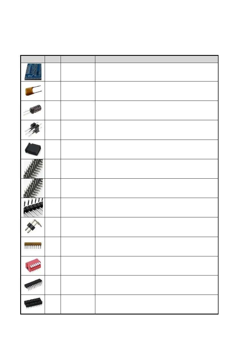
Thefollowingcomponentsare requiredto assemblethe module. Header pinsJP1
and JP2,and P1 toP4 may needto be cut from longerstrips.
Image Qty Reference Description
1
PCB Printed circuit board SC103 Z80PIO
4
C1, 2, 3, 4 Capacitor 100nF,ceramic,leadspacing =2.54mm
1
C5 Capacitor 100uF,electrolytic,lead spacing=
2.54mm(radial) or14mm (axial)
1
JP1 and JP2 Pin header, male,2 rowsx 2 pins, straight
2
JP1 and JP2 Jumper shuntfor pinspacing = 2.54mm
1
P1 Pin header, male,2rows x 39 pins, angled (2nd
rowoptional)
1
P2 Pin header, male,2rows x 13 pins, angled
1
P3 Pin header, male,1row x 29pins, angled
1
P4 Pin header, male,1row x 2 pins, angled
1
RP1 Resistor pack8x10k, SIL,9-pin
1
SW1 DIP switch,6 way,piano style
1
U1 74HCT688, 8-bitidentitycomparator, PDIP20
1
U1 socket 20pin PDIPIC socket0.3" wide
 Loading...