EasyManuals Logo

ZiLOG Z80 User Manual

ZiLOG Z80
34 pages
To Next Page IconTo Next Page
To Previous Page IconTo Previous Page
Page #19 background image
18
Step 4
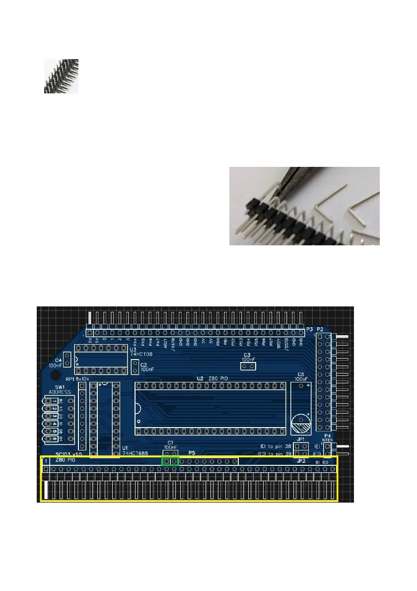
Fit andsolder connectorP1.
Youcan fit just a singlerowheader asused by the RC2014standard bus.The only
reasons forthe second rowis to provideadditional powersupply pins, make the
modulethe same height as the others andto increase stabilityof the module.
Toprepare the header, itshould first becut
to length (ifstarting witha strip more than
39pins long)and thenunwanted pins must
be
removed.
If
you
want
to
make
the
board
as
easy
to
insert
and
remove
as
possible,
you
canremoveall thepins inthe secondrow
exceptthoseshown onthe schematicas
usedand indicated below ingreen.
Takecare to ensurethe pinsare parallel tothe circuitboard so thatthe board willbe
vertical whenplugged into abackplane.

Other manuals for ZiLOG Z80

Questions and Answers:

Question and Answer IconNeed help?

Do you have a question about the ZiLOG Z80 and is the answer not in the manual?

ZiLOG Z80 Specifications

General IconGeneral
ManufacturerZiLOG
Introduction Year1976
Clock Speed2.5 MHz to 20 MHz
Data Width8-bit
Address Width16-bit
Instruction SetZ80
Transistor Count8, 500
Package40-pin DIP
CategoryMicroprocessor
Memory Address Space64 KB
Voltage Supply5V

Related product manuals