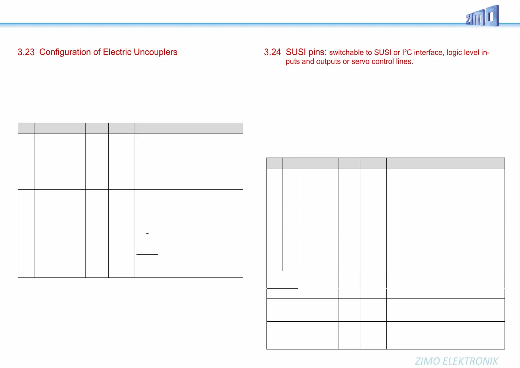
Page 42 MS - SOUND decoders MS440 to MS990 and MN - NON-SOUND decoders MN170 to MN340
System KROIS” and “System ROCO”
If one or two of the function outputs FO1 - FO8 is assigned to the uncoupler function (CV #127 for FO1
etc.), the control of the couplings as well as the entire uncoupling process is defined by
CVs #115 and #116
These CVs limit the time it is switched on (to prevent overheating), define a hold-in voltage if required (i.e.
System “Roco”) as well as the automated coupling unloading and train disengagement.
It is recommended to use the following settings for the Krois system: CV #115 = 60, 70 or 80; these
settings will limit the pull-in time (at full track power) to 2, 3 or 4 seconds respectively.
Uncoupler control
Activation time
or
CV #115
can be used as alternative
“second dimming value.”
(Dimming 0 % - 90 % using
ones digit;
tens digit must be 0)
The uncoupler function is only active if “uncoupler” is
selected (value 48) in one of the CVs #125 – #132,
#159, #160:
Tens digit (0 – 9): Time in seconds the coupler re-
ceives full voltage (pull-in time):
Value: 0 1 2 3 4 5 6 7 8 9
sec: 0 0.1 0.2 0.4 0.8 1 2 3 4 5
Ones digit (0 to 9): PWM – voltage reduction (0 % to
90 %) to control the coupling during the pull-in time
(ROCO coupling, not KROIS).
Automatic
Disengagement
during uncoupling
=
“Automatic uncoupling“
Tens digit (0 - 9): Length of time the loco should move
away (disengage) from the train; coding as in CV
#115.
Ones digit (1 – 9) x 4 = Internal speed step applied for
disengagement (Acceleration per CV #3)
Ones digit = 0: Standstill
Hundredths digit
= 0: No unloading.
= 1: Coupler unloading: engine moves toward train
in order to relieve coupler tension, before uncoupling
and disengaging from the train.
EXAMPLE:
CV #115 = 60 (driving off after disengagement for 2
sec), and
CV #116 = 155 (active pushing to disengage, speed
step 20, 1 sec)
Notes to automated uncoupling with coupler-unloading and train disengagement
- The automatic train disengagement is active if the tens digit in CV #116 is other than 0; if desired with prior coupler
unloading (when CV #116 > 100).
- The automatic train disengagement (or the preceding coupler unloading) is started at the same time the coupling is
activated, but only if the train is standing still (speed 0); if the train is still moving, the uncoupling, unloading and
disengagement procedure will not start until the train comes to a full stop.
- The procedure terminates when the “temporary” function key is released (or pressed again if in latched mode), or
when the predetermined times (CV #115 for the coupling, CV #116 for the disengagement) have expired.
- The uncoupling and disengagement process is aborted immediately if the speed regulator is operated at the same time.
- The driving direction for the train disengagement is always according to the direction set; directional settings in the
“special effects” definition for uncoupling will not be applied.
The "SUSI pins" described in this manual are multi-functional; they can be used either as SUSI interface, as I2C
interface, as logic level outputs or inputs or as servo control lines *
)
. The "SUSI pins" are located on PluX or MTC
connectors, or (for wired types) on solder pads, see connection diagrams, chapter "Technical.Data, ...".
*) In case of "small" decoders (H0, N, TT, etc.) the SUSI pins in alternative application are the only possibility to
connect servos; large scale decoders on the other hand have dedicated servo pins; only if these are not sufficient,
the SUSI pins are used for additional two servos.
By default, the SUSI data and clock lines are active on the "SUSI pins", in case, logic level outputs shall be
active instead, set CV #124 Bit 7 = 1 (value 128) (Bit 7 in add.to other possibly set bits)
These logic level outputs are then always numbered as those following the "normal" outputs: e.g. on an MS450
which has 10 "normal" function outputs (Lfor, Lrev, FO1 - FO8), the logic level outputs are addressed as FO9,
FO10, whereas on an MS440 they are addressed as FO7, FO8.
The CVs listed below define all alternative uses of the "SUSI pins". In factory default state (unless otherwise
specified by Sound-Project) these CVs are normally set = 0, so that the "SUSI-Pins" actually form the SUSI
interface. In the query order of the CVs the following applies:
the first CV <> 0 (or bit 5 in CV #393) determines the application; subsequent CVs have no effect.
Order: logic level outputs / logic level ("reed") inputs / I²C interface / servo control lines / SUSI
Shunting key func-
tions (not
in use)
Switch SUSI -
logic level outputs
Bits 0 - 4, 6: Selection of a shunting key to
ACTIVATE HALF SPEED:
Bit 5 = 1: “DC stopping”
Bit 7 = 0: SUSI-interface active
= 1: Logic level function outputs instead of SUSI
Entries in the following CVs thus have no effect.
ZIMO Config 5
switch inputs
Bit 0 – Bit 4: various sound settings (see chapter 5.6)
Bit 5 = 1: reed switch inputs activated instead of SUSI
Entries in the following CVs thus have no effect.
Bit 6 = 1: 4x extension of the steam interval
Bit 2 = 1: I²C activated instead of SUSI.
Entries in the following CVs thus have no effect
for Servo 1,
for Servo 2,
for Servo 3,
for Servo 4.
Settings for operation of the first 4 servos: see chapter
"3.25 Servo Configuration".
If it is a "SUSI pin", it will be redefined to servo control line at
the same time: for "small" decoders servo-1 and servo-2 to
"SUSI pins", for large scale decoders the last ones (e.g. -7
and -8 for MS990 > 0: Servo control line to "SUSI-Pin
ATTENTION:
Autom. adjust-
ment possible
Alternative (to be
preferred for new
projects) Setting
the "SUSI" appl.
= 11: SUSI pins as logic level outputs (see above)
= 22: SUSI pins as logic level ("reed") inputs
= 33: SUSI pins as servo control lines
= 44: SUSI pins as "SUSI pins" (same as 0)
= 55: SUSI pins as I2C bus.
If decoder (large
railroad decoder)
has two "SUSI"
connections
As above (CV #201), but for second SUSI connection;
there, however, CV #202 is the only setting option, not just
the alternative).
Use of the
inputs IN1 & IN2,
or IN3 & IN4
Ones
and tens
digit 0, 1,
2, 4
= 11: both "IN "s as logic level outputs (see above)
= 22: both "IN "s as logic level ("reed") inputs
= 44: both "IN "s as input for axis detector
CV #203 ones digit: IN1, tens digit: IN2
CV #204 ones digit: IN3, tens digit: IN4
 Loading...