M X6 3 3 P22 To p V ie w with )( Plu X22
P ro gram mi ,ng pa ds
!do no t to uch
Function output FO3
SUSI Data (Servo 2)
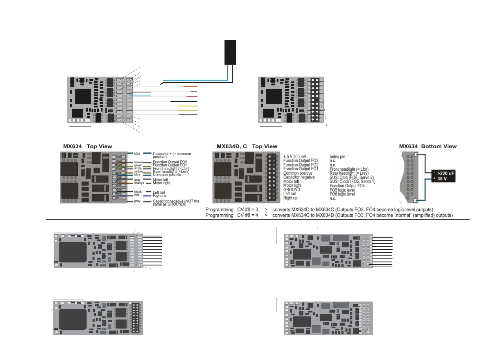
Capacitor positive
Motor right
Motor left
Rail right
Rail left
Function output FO1
Function output FO2
Function output FO5
Function output FO7
Function output FO8
Switch input
SUSI Clock (Servo 1)
GROUND
Stirnl. vorne (= Lvor)
Common positive (+)
--- (Index)
Rear light (= Lrev)
---
Function output FO8
Function output FO4
Function output FO6
P ro gram ming pad s,
do no t to uch !
Function Output FO4
Function Output FO5
Function Output FO6
Function Output FO7
Function output FO1
Function output FO2
Left rail
Rear light (= Lrev)
Rail right
Motor right
Motor left
yellow
green
brown
orange
grey
red
black
Front light (= Lfor)
Com. pos. (+)
white
blue
Cap. pos.
GROUND
SUSI Data (Servo 2) SUSI Clock (Servo 1)
Switch input
Function output FO3
>220 uF
16 V
+ -
The SUSI outputs can alternatively
be used as servo outpus
M X6 3 3 w ith w ires To p Vie w
purple-purple
brown
green
white
yellow
blue (+)
gray
orange
black
red
Speaker - Speaker
Function output FO2
Common positive
Right rail
Function output FO1
Front headlight
Rear headlight
Motor left
Motor right
Left rail
MX 64 0 To p S ide
Program m ing pads,
do not t ouch !
Switch input 1Switch input 2
5 V, 200 mA power supply for small servos (i.e. SmartServo)
MX 64 0 Bottom S ide
F O 8 F O 9
FA5
FA6
FA7
F unction out put s F O 4
F unction out put F O 3
G round
SUSI Data
SUSI Clock
SUSI Positive
logic level outputs
ATT E NT IO N: connect
LED (10 m A) - or
other side to Ground !
MX 64 0D , C Top S ide
+ 5 V, 200 mA max.
Function output FO3
Function output FO2
Function output FO1
Common positive
n.a.
Motor left
Motor right
Ground
Left rail
Right rail
(= with 21-pin plug !)
Index pin
Speaker
Speaker
Front headlight
Rear headlight
SUSI Data
SUSI Clock
Function output FO4
n.a.
n.a.
Switch input 1
Program m ing pads,
do not t ouch !
Switch input 1Switch inpout 2
5 V, 200 mA, for small servo
MX 64 0D , C Bo ttom S ide
F O 8 F O 9
F O 5
F O 6
F O 7
F unction out put F O 4
F unction out put F O 3
G round
SUSI Data
SUSI Clock
SUSI Positive
ATTENTION:
The decoder can be
plugged in from either
side, depending on the
circuit board in the
locomotive.
logic level outputs
ATT E NT IO N: connect
LED (10 m A) - or
other side to Ground !
(= where wires are soldered to)
(which is opposite to “normal” FO’s)
(which is opposite to “normal” FO’s)
Function output FO3
Switch input
Function output FO4