2 / 2 P/N 501-1761ZE-1-05 (EN) • REV 05 • ISS 07JUN13
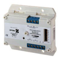
Wiring
Figure 1: Wiring the A50E-2 Line Relay Unit
Setting the address
The A50E-2 Line Relay Unit contains a seven-segment DIP
switch. The switch is used to set the device address in binary
code. The switch may be set to represent any address from 1
to 127.
In the ON position, a switch represents its code value. In the
OFF position it represents a zero. See the table below.
Switch
number
1 2 3 4 5 6 7
Code value 1 2 4 8 16 32 64
To arrive at the address number of a device, add the code
values of all switches that are in the ON position, for example
switches 2, 3, and 6 set to ON represent address 38 (2 + 4
+ 32).
Specifications
Application Indoor use
Operating environment
Temperature
Relative humidity
−10 (±3) to +55 (±2)°C
20 to 95% noncondensing
Indication LED (red) flashing on activation
Operating voltage
20 volt pulsed analog loop
(19.5 to 20.5 VDC).
Max line drop 4 VDC
Standby current 600 µA
Alarm current 700 µA
Relay contact rating
DC
Voltage
Current
AC
Voltage
Current
30 VDC max.
1 A
40 VDC
0.30 A
Power factor resistive load 1 PF
Power factor inductive load
(L/R = 7 mS)
0.4 PF
Regulatory information
Manufacturer
UTC Fire & Security South Africa (Pty) Ltd.
555 Voortrekker Road, Maitland, Cape Town
7405, PO Box 181 Maitland, South Africa
EU authorized manufacturing representative:
UTC Fire & Security B.V.
Kelvinstraat 7, 6003 DH Weert, Netherlands
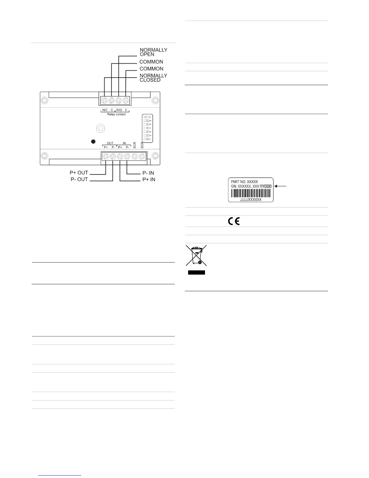
Year of
manufacture
The year of manufacture, in the format YYDDD,
below.
Product type Type A for indoor use
Certification
CPD certificates 0832-CPD-0965
EN 54 EN 54-18:2005
2002/96/EC (WEEE directive): Products marked
with this symbol cannot be disposed of as
unsorted municipal waste in the European Union.
For proper recycling, return this product to your
local supplier upon the purchase of equivalent
new equipment, or dispose of it at designated
collection points. For more information see:
www.recyclethis.info.
 Loading...