© 2013 UTC Fire & Security. All rights reserved. 1 / 2 P/N 501-1761ZE-1-05 (EN) • REV 05 • ISS 07JUN13
A50E-2 Line Relay Unit Installation Sheet
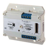
Description
The A50E-2 Line Relay Unit is an addressable device used to
provide one Form C change over dry relay contact to control
external appliances (door closers, fans, dampers, etc.) or
equipment shutdown. The system firmware ensures that the
relay is in the proper ON/OFF state. Upon command from the
control panel, the relay energizes. TB2-6 and TB2-7 provide a
normally-closed relay connection; TB2-7 and TB2-8 provide a
normally-open relay connection. One device address is
required.
Up to 127 devices can be assigned to the loop. All devices
incorporate a binary DIP switch enabling them to be given a
unique address. A red LED indicator illuminates when the unit
has activated.
Installation
Notes
• This module complies with the requirements of EN 54-18.
If the module is used in conditions or circumstances that
do not comply with those tested for and allowed in
EN 54-18, operation may be impaired, and the supplier will
not be liable for any injury suffered or damage caused as
a result. You must contact our technical support
department for advice if the device is to be used in
conditions that differ from those prescribed in EN 54-18.
• This module will not operate without electrical power. As
fires frequently cause power interruption, we suggest you
discuss further safeguards with your local fire protection
specialist.
WARNING: Electrocution hazard. Dangerous voltages may be
present at terminals even when the power is shut off. Take
proper precautions to avoid injury or death.
Note: The A50E-2 Line Relay Unit is shipped from the factory
as an assembled unit; it contains no user-serviceable parts and
should not be disassembled
To install the device:
1. Verify that all field wiring is free of opens, shorts, and
ground faults.
2. Make all wiring connections as shown in Figure 1.
Notes:
• If a 2 in. (51 mm) 1-gang box is used, conduit can enter
the electrical box through only one knockout hole.
• If a 2-1/2 in. (64 mm) 1-gang box is used, conduit can
enter the electrical box through one or both
knockout holes.
Mounting
The A50E-2 can be mounted using any of three methods:
• A DIN rail method for mounting multiple/single units
• Adaptor plates for accessory box mounting
• Single box mounting
The unit can be mounted in a European 100mm square box.
The terminal blocks will accept 14, 16, or 18 AWG wire (0.75,
1.0, 1.5, mm²). Sizes 16 and 18 AWG are preferred.