Do you have a question about the Ziton ZP3 and is the answer not in the manual?
Overview of the ZP3 intelligent fire detection system, its modular design, and scalability for various applications.
Highlights key capabilities of the ZP3 system including automatic contamination adjustment, sensitivity settings, and zone displays.
Lists supported sensors and devices for the ZP3 panel, including wired, wireless, and specialized units.
Explains how the ZP3 system detects fires, raises alarms, and activates building systems for life and property protection.
Describes the ZP3 system architecture, detailing communication paths and components.
Explains the Z-Loop's function, its 2-wire circuit for power and data, and device addressing.
Details the ZP3 panel's 4 serial ports and their programming for various communication functions.
Describes the ZP-NET system for connecting multiple ZP3 panels into a multi-panel network.
Details the modular design of the ZP3 panel, available in 1, 2, and 4-loop models.
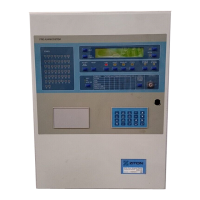
Illustrates and describes the internal components of the basic ZP3 panel.
Provides internal wiring diagrams for the ZP3 panel, showing connections between components.
Details the RS232 port for connecting to external computers for programming and software upgrades.
Describes optional communication boards for additional ports, such as ZP-NET and serial connections.
Details the RS232/RS485 board for connecting to third-party systems.
Explains the ZP3AB-NET1 board for connecting ZP3 panels into a peer-to-peer network.
Describes Z-Loop wiring methods, including class-A return and class-B single direction formats.
Details Z-Loop parameters, including cable screening, and cable sizing requirements.
Explains the 4 built-in sounder outputs, their wiring, and programming for activation on fire alarms.
Details the common fire and fault relay outputs, providing voltage-free contacts for alarm signaling.
Describes the programmable relay board with 8 separate relays for control functions.
Details the monitored output board with 8 outputs for driving fire alarm sounders or control outputs.
Explains the output board with 24 transistor outputs for low-power functions like LEDs or control relays.
Describes the input board with 8 inputs for connection to voltage-free contacts for control functions.
Explains how to navigate and operate the panel's setup menu using the keypad.
Provides a hierarchical view of the panel's setup menu structure.
Details various menu functions for system configuration, including zoning, I/O mapping, and device settings.
Emphasizes the need for a detailed system specification for setup and future maintenance.
Defines software rules for linking inputs to outputs, creating 'cause and effect' schedules.
Lists pre-programmed SystemBus addresses and their functions for panel operations.
Details UserBus addresses for auxiliary boards, defining their point address ranges.
Introduces the Peer-to-Peer 3 Protocol, enabling networking of up to 255 ZP3 panels.
Discusses compatibility issues between different panel software versions and the P2P3 protocol.
Highlights new features in the PP3 protocol, including panel comms enable/disable.
Describes filter types like Fetch Disables Control and Disable Events for managing network traffic.
Explains how to use comms filters to minimize network traffic and optimize bandwidth usage.
Presents a simple schematic of a ZP3 fire detection system with sensors and display panels.
Illustrates the layout of the ZP3 control panel fascia, identifying controls and indicators.
Describes the four common alarm indicators: Fire, Fault, Disabled, and Other.
Explains the operation of the five main controls: Accept, Reset, Silence Alarms, Sound Alarms, Restore Disabled Alarms.
Explains how to read the LCD display's Zone Screen for alarm information by zone.
Details how to read the LCD display's Point Screen for alarm information by device.
Describes the annunciation and operator actions required for a fire alarm.
Outlines the annunciation and operator actions for fault alarms.
Explains how zones, sensors, and outputs can be disabled for maintenance.
Introduces the operator menu for routine functions and system checks via the keypad.
Presents the operator menu structure as a tree, grouping related options.
Details menu functions for time/date setting, reports, lamp/keypad tests, and printer options.
Outlines the owner's responsibility for maintaining the fire detection system's proper working condition.
Details daily and weekly checks to ensure the system is operational at all times.
Emphasizes the owner's responsibility for system maintenance and Ziton's recommendations.
Covers basic requirements for system maintenance, including system specification and log books.
Provides detailed daily and weekly checks for system operational status and LED functionality.
Outlines the schedule for quarterly service, including log book analysis, sensor checks, and configuration checks.
Details the annual service schedule, repeating quarterly checks and adding building change checks.
Explains menu functions for editing disabled devices, viewing disabled status, and enabling/disabling points.
Explains reference group readings to determine device status, health, and type.
Details how readings identify device type, using combinations of polling, device type, and reference readings.
Describes device status reading as an indicator of sensing environmental factors like heat or smoke.
Explains the status indications for the Gas Control Unit using analogue readings.
Provides general information on ZP fire detection systems, emphasizing flexible wiring and simple installation.
Details the panel's mains and earth connection requirements for effective functioning.
Describes the ZP system's use of cables to interconnect various devices like panels, sensors, and computers.
Outlines the four main circuit types used in ZP systems: Z-Address, Serial, Parallel, and DC Control.
Illustrates single panel and multi-panel networked system circuit schematics.
Explains Z-Address lines connecting addressable devices to the panel, providing power and data communication.
Details wiring styles like Style A, B, and C, offering flexibility and low cost for installation.
Describes line isolators for monitoring short circuits on field wiring and maintaining line operation.
Recommends shielded cable for protection against external interference and equipment protection.
Covers the use of unshielded cable where shielded cable is impractical, with AVF mode recommended.
Details Z-Address Line loop length limits based on device types and cable characteristics.
Describes data lines for digital communication between panels and other devices.
Explains RS232 ports for connecting to computers and accessories, typically one piece of equipment per port.
Details RS485/RS422 ports for connections between ZP panels, equipment, and computers.
Describes data lines for digital communication between control panels and ZP accessory boards/printers.
Explains ZP systems operate on 24Vdc for power supply wiring and switched low voltage circuits.
Provides guidelines for sizing DC control cables based on current consumption and volt drop.
| Model | ZP3 |
|---|---|
| Category | Control Panel |
| Type | Fire Alarm Control Panel |
| Display | LCD |
| Manufacturer | Ziton |
| Input Voltage | 230V AC |
| Battery Backup | Yes |
| Enclosure Rating | IP30 |
| Operating Temperature | -5°C to +40°C |
| Relative Humidity | Up to 95% non-condensing |