© 2014 UTC Fire & Security. All rights reserved. 1 / 4 P/N 501-1780ZE-1-10 • REV 10 • ISS 16APR14
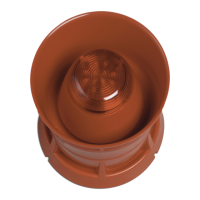
ZP755HAV-2 Addressable Horn Sounder/Visual
Indicator Installation Sheet
Description
The ZP755HAV-2 is an addressable horn sounder/visual
indicator designed for use in Ziton analogue addressable fire
detection and alarm systems.
Note: The visual indicator of this product does not comply with
EN 54-23 and must not be used in fire alarm installations
where fire notification beacons are required.
The device includes a volume control, an address-setting
switch, programmable tone settings, and a pair of jumpers to
select the operating power — from the analogue addressable
loop or an external supply. The device plugs into a base that is
purchased separately. See Table 1 for a list of model numbers.
Table 1: Models
Number Description
Sounder:
ZP755HAV-2R
ZP755HAV-2P
Horn sounder, red
Horn sounder, polar white
Base:
SPB-2R
SPB-2P
Base, red
Base, polar white
Installation
To install the device;
1. Wire the base
2. Set the operating power
3. Set the address
4. Set the mode of operation
5. Set the tone
6. Set the volume
7. Mount the sounder/visual indicator onto the base
The details of each step are given below.
Wiring the base
Connect the loop wiring for the plug-in base as shown in
Figure 1. There is no wiring between the sounder and base.
The base is supplied separately.
Figure 1: Loop wiring for the base
1. Ext. 24 VDC+ IN/OUT
2. Ext. 24 VDC ground IN/OUT
6. Loop − IN/OUT
7. Shield
Setting the operating power
The sounder includes a pair of power selection jumpers, J1
and J2. To select the source of the sounder operating power,
position the jumpers as shown in Figure 2.
Figure 2: Power selection jumper configuration
1. Loop powered 2. External 24 VDC
Note: When using an external power supply, use only one that
is CE and EN 54-4 compliant to power all the sounders on the
same loop.